Solder Pot Alloy Analysis and Contamination Control
A wave solder pot is not a static bath of metal. Every board that passes through it dissolves a little copper, every top-up adds alloy that may be slightly different from what is already there, and every hour at temperature changes the chemistry a little more. The pot is a working alloy system, and the only way to know what it contains is to sample it and analyse it on a schedule. This article covers what happens to the alloy, how to take a representative sample, how to read the report and what to do when the numbers move.
Why the Pot Changes Over Time
Three mechanisms drive the change. The first is dissolution, as copper from the boards and from the plated holes enters the bath. The second is selective oxidation, as the more reactive elements report to the dross on the surface and are removed with it. The third is addition, as ingots or wire are added to maintain the level, often with a slightly different composition from the bath they join.
The result is a bath that drifts in a predictable direction. Understanding which direction each mechanism pushes a given element is what makes an alloy analysis report readable rather than alarming, and it is the reason a single reading is far less useful than a series of them taken under the same conditions.
Copper Dissolution and Its Limits
Copper dissolves into tin rich solder until the bath reaches saturation for the working temperature. A saturated bath stops dissolving and starts depositing intermetallic particles, which appear as a sludge and raise the viscosity. Copper is always the element that moves fastest in wave soldering, and it is the one that most often forces a correction.
The limit is set by the alloy specification and by the effect on the joint. Above the limit the solder becomes sluggish, the fillets turn grainy and the risk of bridging rises. Our plating thickness guide explains how the amount of copper present on a board sets how much can be dissolved per panel.
Other Contaminants: Iron, Zinc, Gold, Aluminum
Iron usually arrives from poorly maintained pots and pump components, and it forms hard intermetallic particles that abrade the pump. Zinc is the most damaging at low levels and often comes from plated hardware or from a brass fitting in contact with the bath; it makes the solder dull and thirsty and destroys wetting at concentrations far below the copper limit.
Gold dissolves readily and is tolerable in small amounts, but it forms brittle intermetallics if it is concentrated. Aluminum is a strong oxide former and produces a heavy dross and a lumpy bath even in trace amounts, usually from a dropped tool or a component lead that should never have entered the pot.
Sampling Practice for a Representative Result
A sample is only useful if it represents the bath. The pot should be at the working temperature and at rest, the surface dross should be cleared, and the sample should be taken from the working volume rather than from the surface or from the wall. A sample taken immediately after a top-up measures the ingot rather than the bath.
The ladle or sampler must be clean and free of the previous alloy, because a tool that has been used in another pot carries the contamination that the analysis is meant to detect. A written sampling procedure, the same one every time, is what makes a series of reports comparable with each other, and it is the difference between an alloy analysis that supports a decision and one that only adds noise to the file.
Analytical Methods Compared
Optical emission spectrometry and X-ray fluorescence are the two methods a soldering operation is likely to meet. Optical emission gives good accuracy across the full element list and is the usual choice for a formal analysis, while X-ray fluorescence is quick and needs little sample preparation but is less reliable for the light elements and for elements present in trace amounts.
Whichever method is used, the report should state the method, the detection limits and the uncertainty. A result reported to three decimal places from a method with an uncertainty of half a percent is a number without a meaning, and it invites a correction based on noise.
Interpreting an Analysis Report
The first step is to compare each element with the alloy specification, not with the previous report alone. A drifting trend inside the specification is information about the process, while a value outside the specification is a decision point. The second step is to look at the elements together, because a high copper reading with a low silver reading suggests a dilution event rather than a dissolution one.
The third step is to check the sampling date against the production record. A report that reflects a pot state from three weeks ago cannot explain a defect found yesterday, and a defect investigation should use a sample taken after the defect appeared.
Corrective Actions: Dross, Top-Up and Replacement
Small corrections are made by topping up with an alloy that offsets the drift, which for high copper means adding a low copper or copper free material. Larger corrections are made by removing a portion of the bath and refilling it, a procedure that must be planned because it changes the level, the temperature and the chemistry all at once.
Where a contaminant has no practical removal route, the only option is a full replacement. The decision point should be written down in advance, so that the replacement is a planned cost rather than an emergency during a customer order. The same logic applies to a partial drain, which should be scheduled into a maintenance window with the new alloy already on site.
Routine Monitoring Schedule
The interval between analyses depends on the throughput and on the board mix. A pot running heavy copper panels daily needs more frequent checks than one running thin single sided boards, and a pot that is only used occasionally needs a check before each campaign rather than on a calendar.
The schedule should also include the physical checks that the alloy analysis does not cover: dross rate, pump condition, heater performance and the appearance of the solder wave. Recording those observations next to the analytical result gives a fuller picture of the bath than either source alone. Our solder defect notes describe how a contaminated bath shows itself in the finished joints.
Record Keeping and Traceability
Every analysis should be filed with the date, the pot identification, the sample point, the production lots that ran on that bath and the corrective action taken. That record is what allows a defect to be traced back to a bath condition, and it is also what demonstrates to a customer that the process is controlled rather than merely inspected.
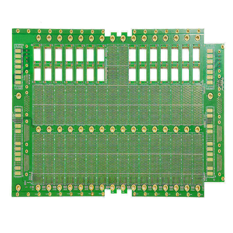
At gopcb that record sits alongside the production process flow for each order, so that the alloy state at the time of manufacture is known. The condition of the finished surface is judged against our surface finish criteria, and our quality guide describes how a finish defect is classified.
FAQ
How often should a solder pot be analysed? Often enough that the trend is visible before the limit is reached, which for a busy wave line is usually monthly and sometimes weekly. The right answer comes from the drift rate measured on that specific pot.
Can contaminated solder be cleaned in place? Some elements can be reduced by dilution or by removing dross, but there is no practical way to remove zinc or aluminum from a tin bath at the bench. Those cases end in a replacement.
Does lead free solder need different limits? Yes. The alloy systems differ, the working temperatures are higher, and the dissolution behaviour of copper and of the surface finish metals is not the same, so the limits should come from the alloy supplier rather than from an older tin lead specification.