Spirometer Circuit Design: Pressure to Flow
A spirometer turns a pressure difference into a flow, and a flow into a volume. The electronics are simple in principle, and the accuracy of the instrument depends almost entirely on the sensor, the conditioning around it and the calibration of the whole path.
What the Instrument Measures
The patient exhales through a mouthpiece that presents a known resistance to the airflow. The pressure difference across that resistance is proportional to the flow, and integrating the flow over time gives the volume.
The clinically interesting numbers are the peak flow, the volume in the first second and the total volume. Each of them is derived from the same measurement, so an error in the flow appears in all of them.
Sensor Options
A differential pressure sensor is the usual choice for a handheld instrument, because it is small, cheap and does not obstruct the airway. A turbine or a hot wire sensor offers a different trade between sensitivity and resistance.
The sensor has to be compatible with exhaled air, which is warm and saturated with moisture. A sensor that drifts when it is wet will not hold its calibration through a clinic session.
The Differential Pressure Sensor
A piezoresistive sensor contains a diaphragm and a bridge, and its output is a small differential voltage proportional to the pressure. The usable range might be a few kilopascals, which sets the sensitivity of the whole instrument.
The sensor is usually ratiometric, meaning its output scales with the supply. That property is useful, because it allows the analog to digital converter to use the same supply as its reference and cancel the variation.
Signal Conditioning
The sensor output is amplified to fill the input range of the converter, which improves the resolution of the measurement. A gain of about ten is typical for a sensor with a five volt output range and a three volt converter.
The amplifier has to be chosen for a low offset drift, because an offset that moves with temperature appears as a flow that is present when the patient is not breathing. Chopper stabilised amplifiers are common for that reason.
Filtering and the Anti Alias Stage
The signal contains the breathing waveform and the noise of the airway, and the sampling rate has to be high enough to capture the rapid rise at the start of a forced expiration. A single pole filter at around twenty hertz limits the noise without distorting the waveform.
The filter is placed before the converter, not after it. A digital filter cannot remove the aliased content that a fast edge produces when it is sampled at a rate that is too low, and that content appears as a false feature in the flow curve.

Converter and Reference
A twelve bit converter with a sampling rate of a few hundred samples per second is sufficient. The reference has to be quiet, because the measurement resolution is a fraction of a millivolt and the supply in a handheld instrument is not clean.
Where a high resolution is needed, an external converter with an integrated reference is easier to design with than an internal one. The layout and the decoupling of that part decide whether the extra bits are real, as discussed under <a href="https://www.gopcba.com/adc-clock-stability-design/” title=”ADC stability”>ADC stability.
From Pressure to Flow
The relationship between flow and pressure difference is not linear, because the flow through the mouthpiece becomes turbulent at higher rates. The firmware applies the square root relationship and the correction factors measured during calibration.
Temperature and humidity affect the result as well. The volume reported by a spirometer is referenced to body temperature and pressure, saturated, and the correction is part of the calculation rather than a refinement.
Calibration
The instrument is calibrated with a syringe of known volume. The syringe is emptied through the mouthpiece at a defined rate, and the volume reported by the instrument is compared with the volume delivered.
Several flow rates are used, because a single point calibration hides the non linearity. The correction curve that results is stored in the instrument and applied to every measurement.
Display and Interface
The display shows the flow volume curve and the derived numbers. A small graphical display is enough, provided the update rate is high enough for the curve to look continuous to the user.
The interface covers the buttons, the battery indication and the connection to a computer or a phone. The data path is part of the medical record in a clinical setting, so the format has to be defined rather than improvised.
Power Management
The instrument is battery powered and used intermittently. The processor, the display and the sensor dominate the consumption, and the analog section can be switched off between measurements.
The supply for the analog section should be regulated separately from the digital one. A shared regulator couples the processor current into the sensor supply, and the resulting noise appears directly in the flow signal.
Layout of the Sensor Front End
The sensor and the amplifier form a high impedance, low level circuit, and the rules for a mixed signal design apply to it. The trace from the sensor to the amplifier should be short, guarded by ground and kept away from the display and the switching supply.
The ground of the analog section should be a quiet area joined to the digital ground at one point. A quality review of that arrangement before the layout is released is cheaper than the drift that follows from it.
Test and Production
Every unit is verified with the calibration syringe before it leaves the line, and the result is recorded against the serial number. A unit that drifts outside the tolerance is reworked or rejected rather than shipped with a note.
The mechanical assembly is part of the measurement. A leak between the mouthpiece and the sensor changes the pressure difference, and a leak path is the most common cause of an instrument that reads low.
Process Control and Verification
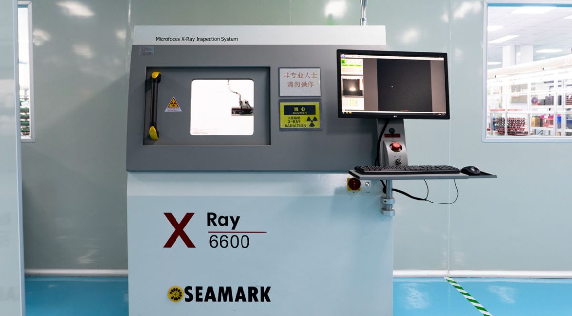
On a design of this kind, differential pressure is the item that decides how the rest of the board is arranged. The measurements that matter are the repeatable ones: conductor width and spacing, annular ring, finished hole size, plating thickness and surface finish are all verifiable on a coupon that travels with the panel. Running a first article through the same checks as the production panel confirms that the two agree, and that comparison is the cheapest form of process control available at prototype stage.
Keeping a sample from the panel turns a dispute into a measurement, because the same coupon can be re-examined by both parties without rebuilding the batch.
Process Control and Verification
On a design of this kind, differential pressure is the item that decides how the rest of the board is arranged. The measurements that matter are the repeatable ones: conductor width and spacing, annular ring, finished hole size, plating thickness and surface finish are all verifiable on a coupon that travels with the panel. Running a first article through the same checks as the production panel confirms that the two agree, and that comparison is the cheapest form of process control available at prototype stage.
FAQ
Why is a differential pressure sensor used? Because it measures the flow without obstructing the airway, and it is small and cheap enough for a handheld instrument.
Why is the flow not linear with pressure? Because the airflow becomes turbulent at higher rates. The square root relationship and the calibration curve account for it.
How often is calibration needed? It is verified before each clinical use where the procedure requires it, and the instrument is recalibrated on the schedule the manufacturer specifies.