Solder Wicking Defects in Through-Hole and Cable Joints
Solder is supposed to stay where the joint is, and most of the time it does. Occasionally it does the opposite: it climbs up a pin, up a wire or into a stranded conductor, away from the connection that needed it. The result is a joint that is starved at the pad and stiff where it should be flexible. Solder wicking is a common defect on mixed technology boards and cable assemblies, and it is easier to prevent than to rework.
What Solder Wicking Is
Wicking is the migration of molten solder away from the intended joint, driven by capillary action along a narrow path. On a through-hole component it travels up the lead and away from the barrel; on a wire termination it travels under the insulation and into the strands. In both cases the solder ends up where it does no good.
The defect is easy to miss because the visible joint may still look acceptable. The problem is what has been taken away from it. A joint that has lost a fraction of its alloy to a lead or a cable has less fillet, less barrel fill and less mechanical margin than the drawing assumes.
Capillary Action and the Driving Forces
The mechanism is the same one that fills a plated hole: a narrow gap, a wetting surface and a driving force. The difference is direction. In a properly designed joint the capillary path draws solder into the barrel, whereas wicking follows an unintended path such as the annulus between a lead and a plated barrel, or the space between wire strands.
Three conditions normally combine. The path must be narrow enough to generate capillary pressure, the surfaces must be wettable, and there must be enough heat and time for the solder to travel. Remove any of the three and wicking stops, which is why the countermeasures divide neatly into geometry, surface condition and thermal profile.
Solder Wicking in Through-Hole Assembly
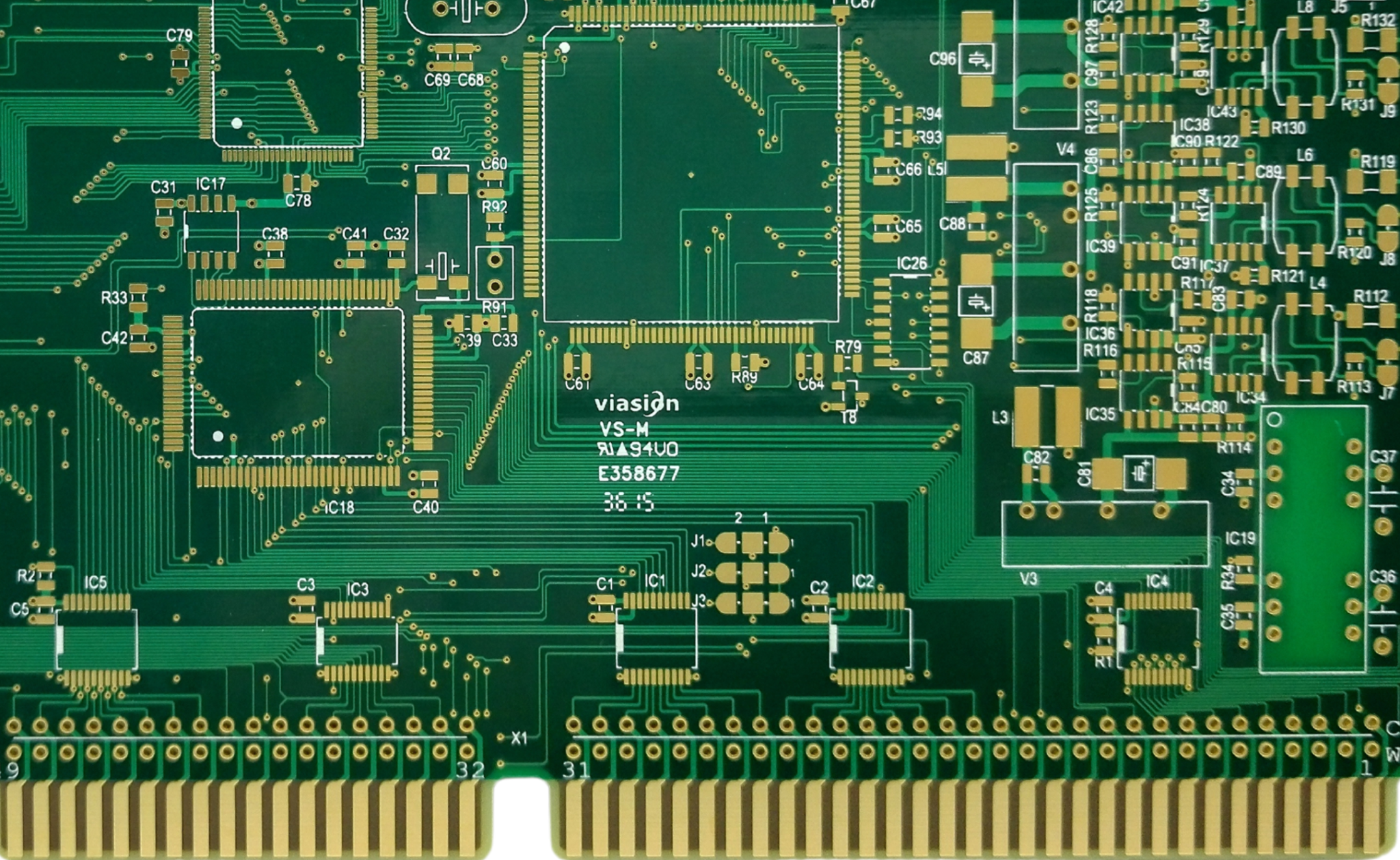
On a through-hole joint, the most common route is the clearance between the lead and the barrel. If that gap is too large, solder can travel up the pin on the outside of the barrel rather than filling the hole. If the pad and the lead are both clean and well fluxed, the alloy has every incentive to keep moving upward.
Preheating from the component side worsens the effect, because the lead is hotter than the barrel and solder prefers the warmer surface. Where a component body sits close to the board, solder can also climb under the body and become trapped, producing a hidden defect that only appears when the joint is sectioned. Owners of plated hole construction should consider the lead-to-hole ratio as part of the joint design rather than a fabrication detail.
Solder Wicking in Cable and Wire Terminations
Cable terminations are more exposed. Molten solder follows the strands of a stranded conductor far more readily than it travels along a solid wire, and once it passes the point where the insulation ends, the flexible section becomes rigid. Bending then concentrates stress exactly at the boundary between the wetted and dry strands, and the wire eventually fractures there.
This is why the standard practice is to restrict solder to the terminal and to control the distance it may travel beyond it. The ideal joint has a short, controlled amount of wicking no further than one strand diameter past the terminal, with the strands still visible and still flexible further along the cable.

Consequences: Starved Joints and Stiff Wires
A starved through-hole joint has a fillet that is thinner than the drawing requires and a barrel that is only partially filled. Electrically it may measure fine, but mechanically it is weaker and thermally it runs hotter because the current path is smaller. Under thermal cycling, a partially filled barrel is one of the first places a crack begins.
On cables, the consequence is mechanical rather than electrical. A rigid section in a flexible cable is a stress riser, and vibration turns it into a fatigue failure. Because the failure occurs inside the insulation where it cannot be seen, the defect typically surfaces as an intermittent open in the field, long after the assembly passed its inspection.
Process Causes and Prevention
Excess heat and time are the usual process causes. A higher-than-necessary iron temperature, a long dwell or an oversized solder wave all give the alloy more opportunity to travel. Reducing the temperature and shortening the contact time is the first correction, followed by adjusting the flux so that activity is sufficient without being aggressive.
Flux selection deserves care because an over-active flux cleans surfaces far up the lead and actively encourages wicking. For cable work, a solder with a narrow plastic range and a fast freeze shortens the window in which travel can occur. For barrel fill, raising the preheat from the solder side, rather than the component side, biases the temperature gradient in the helpful direction.
Design and Material Choices
Geometry is the most durable control. Keeping the lead-to-hole clearance within a narrow range limits the capillary path, and specifying a heat-shrink sleeve or a solder stop on a cable physically blocks travel beyond a chosen point. Where a component must sit flush to the board, a standoff or a spacer keeps solder from climbing under the body.
Surface finish matters as well, because a very wettable finish with a large surface area gives solder more to hold on to. Nickel barriers on lead frames and controlled finishes on pins reduce travel, while a plated barrel with a slightly rougher wall provides more resistance than a perfectly smooth one. Material and geometry choices are cheaper than rework, and they are made once at design time.
Inspection and Rework Limits
Inspection has to look at the joint and away from it. A fillet that looks acceptable but sits on a lead that is coated in solder well above the pad should be treated as suspect, and the same applies to a wire that feels stiff past the terminal. Visual criteria should state how far solder may travel, and inspectors need a go and no-go sample to apply it consistently.
Rework is possible but limited. Removing excess solder from a lead with braid risks removing the solder holding the joint together, and on a cable it is almost impossible to restore flexibility once the strands have been wetted. In practice the correct action on a badly wicked cable termination is to cut the connection back and remake it. Recognizing which defects are repairable and which are not is part of quality judgement, and the failure modes that result from getting it wrong are documented in this overview of solder defect signatures.
Specification and Training
A written specification should state the maximum permissible travel as a distance or as a fraction of a dimension, and it should distinguish between through-hole and cable applications because the acceptable limits differ. Absolute prohibitions are easier to apply than qualitative descriptions, and they are far easier to defend when a supplier disputes a lot.
Training matters because the defect is subtle. Operators who understand why a solder-coated lead is a problem, rather than simply being told it is one, spot it more reliably and report the process conditions that produced it. Photographs of acceptable and unacceptable travel, taken from the actual product, are more useful than any standard illustration.
FAQ
Is some wicking on a wire normal? Yes, a small amount is unavoidable and is usually accepted up to about one strand diameter beyond the terminal. The problem begins when solder passes the insulation boundary or travels far enough to stiffen the flexible section, because that creates a stress concentration where the cable will eventually crack.
Can wicking be removed after soldering? Excess solder can sometimes be removed from an accessible lead with braid or a desoldering tool, but the process risks damaging the joint that remains. On stranded cable the wetted strands cannot be restored to their original flexibility, so the practical remedy is to cut back the connection and remake it with better process control.
Does a larger hole make wicking worse? A larger clearance between the lead and the barrel narrows the effective capillary path in a way that can encourage solder to travel along the pin rather than fill the hole. Keeping the lead-to-hole ratio within a controlled range is one of the most effective ways to prevent the defect at the design stage.