Placement Accuracy: Design Rules and Process Limits
A placement machine is judged by where it puts the components. The specification that a machine manufacturer quotes is measured under ideal conditions on a glass plate, and the accuracy that a product experiences depends on the board, the fiducials, the component and the program.
The question a production engineer has to answer is therefore not what the machine can do, but what the process is doing on this product. That is a capability question, and it is answered with measurements from the line.
Accuracy and Repeatability Are Different
Accuracy is how close the machine gets to the intended position. Repeatability is how closely it repeats itself when asked to do the same thing again. A machine with modest accuracy and excellent repeatability can be calibrated into a good process, while one with good accuracy and poor repeatability cannot.
The distinction matters when a problem appears. An offset that is consistent across the board is a calibration or a fiducial issue; a scatter that changes from board to board points at repeatability, which is a mechanical or a vision problem.
Fiducials and the Reference System
The machine positions everything relative to fiducials on the panel. Two fiducials far apart define the translation and the rotation, and their accuracy therefore limits the accuracy of every placement on the board.
A fiducial that is poorly shaped, partly covered by mask or inconsistent in contrast makes the vision system work harder and less accurately. Panel level fiducials and local fiducials next to a fine pitch device are used together where the panel scale and rotation correction is not enough on its own.
Measuring Placement Accuracy
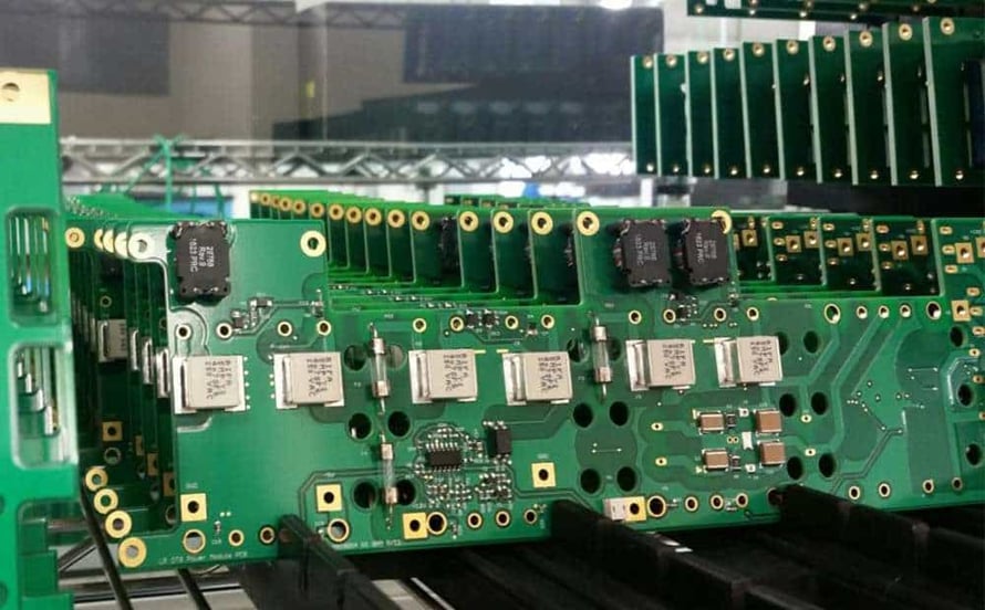
The measurement is made by placing components and then measuring where they actually landed. An automated optical system can do this on a production board, and a coordinate measuring machine can be used on a sample where the requirement is tight.
The result is reported as an offset in X and Y and a rotation for each component, and the data is only useful if it is grouped. Grouping by component type and by position on the panel shows whether the error is systematic or local, which is the first step in correcting it.
Process Capability and Its Limits
Process capability expresses the spread of a measurement against the tolerance. For placement, the tolerance is set by the pad geometry: a component must land within a fraction of the pad width for the solder to form properly.
A capability index above the accepted threshold means the process will produce acceptable placements with a margin. One that is close to the threshold means the process is acceptable but sensitive, and any change in the material or the machine will push it out. Measuring the capability on the real product is therefore the evidence that the tolerance will be met in production rather than only on the first article.
Nozzle Calibration and Its Drift
The nozzle is the physical interface between the machine and the component, and its condition affects both the pick and the place. A worn tip holds the component slightly off centre, and the error appears as a rotation or an offset that varies with the component.
Nozzle calibration checks the position of the tip relative to the head, and it should be repeated at intervals because the tip wears and the machine’s own reference can drift. A calibration performed during a break in production is cheap; discovering the drift through a defect rate is not.
Component and Feeder Contributions
Not all of the error comes from the machine; feeder setup and the component tape contribute their own share. A component that is not centred in its pocket, a tape that does not peel cleanly and a feeder that advances slightly differently each cycle all introduce variation.
Those contributions are visible in the grouped data. A single component type with a wide spread points at the tape or the feeder, while a spread that follows the position on the panel points at the machine. Separating them is what prevents a machine being adjusted to compensate for a feeder problem, which would then make the good feeders wrong.
Vision Systems and Their Settings
Most machines use a vision system to centre the component before placing it. The settings for that system, including the lighting, the threshold and the pattern, determine how accurately the centroid is found.
A component with a shiny or an unusual surface can confuse the vision system, and the resulting placement error is consistent for that component and absent for others. The settings should be verified when a new component is introduced, and the verification should include the worst case in the reel rather than the first part picked.
Continuous Monitoring
Placement accuracy can be monitored in production by measuring a sample of boards, and the trend is more informative than the individual result. A slow drift indicates wear or a change in the fiducial quality; a sudden step indicates that something was changed.
The measurements should be recorded against the machine and the product, and the same discipline described for process tolerances applies to the placement data, so that a comparison between machines is possible. That comparison is often the fastest way to find a problem, because two machines running the same product should produce similar results, and the same logic applies to the other process measurements tracked in quality control.
Board Support and Its Effect
The board has to be held flat where the component is placed, and a board that flexes under the placement force will receive the part at a different height in different areas. Support pins and a tooling plate are the usual solution.
The support also affects the measurement, because a board that is held at a different height changes the focus of the vision system. Where the accuracy data shows a variation that follows the panel position, the support is one of the first things to check. Keeping the sequence under control is the same principle used in quality control for any other measurement.
Measurement Frequency and Sample Size
A single measurement says very little about a process. The sample has to be large enough to show the spread, and the frequency has to be high enough to catch a drift before a batch is affected.
A reasonable starting point is a small sample from every build, with a larger study when a new component or a new machine is introduced, and the sample should be taken at the same point in each run so that the results are comparable. The data from the routine samples then forms a control chart, and a shift on that chart is the signal to investigate rather than to wait for a defect.
Process Control and Verification
On a design of this kind, placement accuracy is the item that decides how the rest of the board is arranged. A stack-up that is drawn rather than described removes most of the ambiguity from a quotation, and it lets the fabricator price the board against the dielectric and copper weights that will actually be used. Where the requirement is not written down, the shop supplies its own default, and the default is chosen for the process rather than for the design.
FAQ
How accurate does placement need to be? Within a small fraction of the pad width for the smallest component, which on a fine pitch device means a tolerance of tens of microns.
Can accuracy be improved by slowing the machine? Sometimes, because the settling time of the head increases. It is a temporary measure that costs throughput and does not fix the cause.
Do local fiducials replace panel fiducials? No. They correct the local area, and the panel fiducials are still needed to establish the overall reference.