Android Core Board Design for Compact Embedded Products
An Android core board bundles the application processor, DRAM, eMMC storage and the main power tree into a compact module, so most of the product design effort moves to the carrier board underneath it. Treating that module as a plain connector-based part is the fastest way to fail. The device still imposes strict power sequencing, clock, thermal and high-speed interface requirements on everything around it. This guide covers the decisions that determine whether an Android core board design reaches volume production on the first pass.
Dividing Work Between Module and Carrier
A core board is designed by its vendor to solve the hardest part of the problem: DDR routing, processor decoupling and the core power rails sit inside the module on a high-density stackup. Everything that changes from product to product, such as Ethernet magnetics, an audio codec, USB connectors, camera connectors, card slots and the DC input stage, belongs on the carrier board. Drawing that line early keeps the carrier board simple, two or four layers in most cases, which shortens layout time and keeps the cost of a respin low.
Vendors publish a reference schematic for each module, and it is a starting point rather than a finished design. Read it critically: check which nets carry series resistors, which rails must come up in which order, and which unused pins must be terminated rather than left floating. A carrier board that omits a required pull-up on a strapping pin can boot into the wrong mode, and the symptom usually looks like a software fault rather than a hardware one.
Core Board Power Sequencing
Core board power sequencing is the item most often underestimated. The module datasheet specifies the order in which rails must rise, typically core voltage before I/O voltage and DDR rails last, plus the delay required between them. Many modules integrate their own PMIC and accept a single input rail, which removes most of the burden, but the carrier board still has to guarantee that the input rail is clean, present before any enable signal, and able to supply peak transient current rather than only the average figure.
Where the carrier board generates additional rails for peripherals, sequence them with the module rather than independently. Feeding a 3.3 V sensor rail before the module I/O rail can forward-bias internal protection diodes across the processor. A load switch with an RC delay, or a small sequencer with an enable chain, solves the problem for a few cents. Add a reset supervisor so the module only leaves reset after every rail is inside tolerance, and follow power plane splitting rules when several rails share one copper area.
High Speed Interface Routing to Peripherals
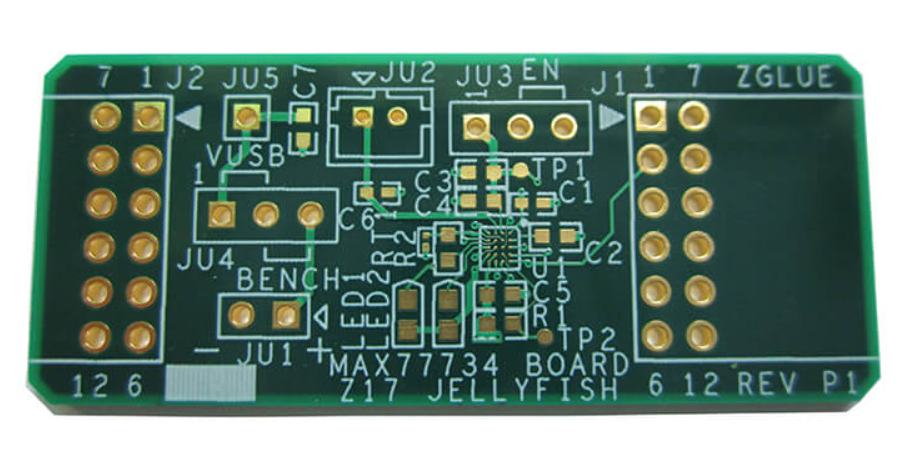
High speed interface routing on a carrier board is easier than inside a module, but it is not free. USB 2.0 pairs, MIPI CSI lanes and SDIO buses all impose impedance, length and reference plane requirements. Keep 90 ohm differential pairs on a single layer where possible, route them over unbroken ground, and avoid stubs. On a two-layer carrier board this usually forces one layer to be almost entirely ground, which is acceptable when the design is planned that way from the beginning. See high frequency trace routing for the underlying rules.
Consistency matters more than absolute length. Two lanes of the same MIPI pair should match within a few tens of mils, and the intra-pair skew budget is tighter still. If a connector forces a detour, compensate on the shorter side rather than scattering serpentine sections along the route. Verify the first prototype with an eye diagram, or at least confirm that the camera streams without dropped frames at the target resolution and frame rate for an hour.
Clock and Reference Timing
The module normally carries its own main oscillator, but peripherals often need separate references. Ethernet PHYs, audio codecs and camera sensors expect a clean clock with low phase jitter. Place the crystal or oscillator close to the device that consumes it, ground the load capacitors to the same local ground, and guard the trace with ground on both sides. A reference that runs through a noisy area shows up as audio hiss or as link errors that appear only at temperature extremes.
For products that need 32.768 kHz timekeeping, treat that net as a sensitive analog signal. Route it away from switching nodes, keep it short, and avoid running it underneath the module where switching currents circulate. If the module provides a buffered clock output, prefer it to placing a second crystal on the carrier board.
Thermal Design under Sustained Load
Thermal design for a core board is dominated by the module itself. Under sustained processor load the module can dissipate several watts inside a footprint of a few square centimeters. Provide a copper pad or a small metal area on the carrier board directly beneath the module thermal pads, tie it to an internal ground plane with a generous number of vias, and allow conduction into the enclosure or a heatsink where the product permits it. Airflow through a vented case is often enough, but sealed plastic enclosures need designed conduction paths.
Measure rather than assume. Instrument the first prototype with a thermocouple or a thermal camera and run the worst-case workload at the maximum ambient temperature specified for the product, then keep margin. Throttling that appears at 70 degrees Celsius on an open bench will appear at 45 degrees inside a sealed box, and the fix is much cheaper before the enclosure tooling is cut.
Layout, Bring-Up and Manufacturing
Give the carrier board a disciplined layout sequence: place connectors and the module first, route high-speed interfaces before lower priority nets, and keep each switching converter compact. Follow placement order and pad positioning practice so that the power stage and its feedback network never get scattered during rework. Expose test points for every module rail, for reset and for the boot mode strapping pins, because a few extra pads turn a two-day debugging session into a twenty-minute measurement.
Plan for manufacturing as well. Specify the module footprint exactly as the vendor defines it, including courtyard and keep-out area, and confirm that the placement machine can handle the module without special tooling. Check that the module moisture sensitivity level matches the reflow profile used for the rest of the assembly. gopcb assembles module-based carrier boards in small and medium volumes and can review the interface plan before layout begins.
FAQ
Can an Android core board run from a single 5 V supply? Most modules accept one input rail and generate their internal voltages, but that rail must survive peak transients of several amperes while staying inside tolerance. Check the minimum input voltage during load steps, not only the nominal value, and size the bulk capacitance accordingly.
How many layers does a carrier board need? Two layers are enough for a simple product when one layer is almost entirely ground. Add a third or fourth layer once the board carries MIPI lanes, USB high speed or several switching converters, because a solid reference plane costs less than debugging intermittent interface errors.
What should be tested on the first prototype? Verify every rail and its sequencing, confirm boot mode strapping, check crystal frequency and jitter, and run the interfaces at full speed for at least an hour. A thermal soak at maximum ambient temperature belongs in the same session, since layout changes are cheapest before the enclosure is finalized.