
Constraint Driven PCB Layout in Modern Design Tools
Modern layout tools no longer rely on the designer remembering every rule. Instead, rules are captured as reusable constraints that the editor enforces while routing and that a verification pass checks at the end. Constraint driven PCB layout changes the workflow from drawing traces to encoding intent, and that shift is what makes complex boards repeatable across engineers and across revisions.
What Constraint Driven Layout Means
A constraint is a machine readable statement of intent: this differential pair must be 90 ohm plus or minus ten percent, this group of nets must match length within 50 mils, this region must keep 20 mils clear of the board edge. Once the rules are written they apply automatically to every net in the class, including the nets added later when the schematic changes.
The practical benefit appears during revision. When a memory bus grows from eight to sixteen bits, a rule based design extends the constraints to the new signals instead of relying on the designer to remember the original rules. That is the difference between a design that can be maintained and one that must be re-derived each time.
Building the Design Rule Set
Start from the fabricator’s capability, because a rule set that the plant cannot build is worse than no rule set at all. Minimum trace width, minimum clearance, minimum annular ring, drill sizes and solder mask dam width come from the fabrication drawing. Load these as defaults for every layer, then tighten them only where a specific net requires it.
Organize the rules into classes rather than applying them net by net. A clock class, a differential class, a power class and a default class cover most designs, and each class carries its own width and clearance. Review the class membership when the schematic is updated, since a mis-assigned net quietly inherits the wrong rule and the error only appears in verification.
Physical and Spacing Constraints
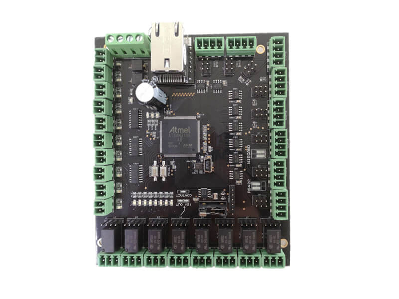
Physical constraints control the geometry: trace width for a given current, via size for a given layer span, pad entry rules for surface mount parts. Spacing constraints control the relationship between objects, such as copper to board edge, copper to hole, or trace to trace across a plane split. Together they define what the layout may look like inside the available area.
Keep the physical rules aligned with the manufacturing process. A design that uses the fabricator’s minimum clearance everywhere leaves no margin for etching variation, and the yield cost appears later as an unexplained price increase. Where the board area permits, use a slightly relaxed clearance for general routing and reserve the minimum for escape areas only. The same discipline applies to PCB pad design standards, which should match the package drawing exactly rather than being adjusted to make routing easier.
Electrical Constraints: Length, Skew and Impedance
Electrical constraints are where the tool earns its place. A length rule defines a target for a bus and a tolerance for each member, a skew rule limits the difference between two nets of a pair, and an impedance rule ties the geometry to a stackup. On a double data rate interface these three rules together decide whether the bus works at the target frequency, and they underpin high frequency trace routing on serial links as well.
Write the rules from the timing budget rather than from habit. A controller with a generous setup and hold window may tolerate more skew than a rule copied from a faster reference design, and an unnecessarily tight rule forces more vias and more serpentine, which adds loss and cost. Document the source of each number so the next engineer can tell which limits are real and which are conservative.

Layer Stackup Definition as a Constraint
The layer stackup definition feeds the impedance rules, so it belongs in the same file as the constraints. Specify each layer’s material, thickness and copper weight, and let the tool compute the trace geometry needed for each target impedance. If the stackup changes, the impedance rules change with it, and the affected traces are re-checked automatically instead of being discovered by measurement.
Freeze the stackup with the fabricator before detailed routing begins. A stackup chosen for electrical convenience alone may be impractical to laminate, and rebuilding it later invalidates every impedance calculation on the board. For high speed designs, the stackup and the constraint set should be reviewed together as one artifact.
Post Layout Verification
Post layout verification compares the finished database against the rule set and reports every violation with its location. Run it before generating the fabrication data, and treat the report as a checklist rather than a formality: some warnings are cosmetic, but a clearance violation or an unmatched length group is a real defect that will either fail at fabrication or fail in the field.
Waive violations deliberately. Every waiver should carry a reason and a name, so that the decision is visible in the release package. That record also helps during the next revision, when a waiver may no longer apply. Cross-check the final database against design guidelines for manufacturable boards as a second opinion.
Working with Fabrication Limits
Constraint sets are only useful if they reflect what the plant can produce. Ask for the standard capability rather than the best case, and note which features move the design into a premium process. Blind and buried vias, very small drills and tight annular rings all have yield consequences that appear in the price and the lead time, not in the design rule document.
Keep a second rule set for the prototype build if the volume design will use a different stackup or a different via technology. Testing the volume construction on the prototype avoids a redesign between pilot and production, which is one of the most expensive changes a program can make.
Team Workflow and Reuse
A constraint set is a team asset. Store it with the project, review changes the way schematic changes are reviewed, and reuse the classes across similar products. When a new design starts from a proven rule set, the first layout passes verification because the rules already describe a construction that has been built before. New engineers then learn the house rules by reading them rather than by inheriting them through conversation, which shortens the time before their first layout can be signed off.
gopcb works with customers who route internally and with teams that hand off the layout, and either way the constraint set travels with the design. Providing the rule set, the stackup and the fabrication drawing together gives the plant everything needed to confirm that the design can be built at the quoted price, and it removes the guesswork that otherwise appears after the first panel is etched.
FAQ
Do small designs need formal constraints? A two-layer board with a few signals rarely needs a full rule set, but the fabrication limits should still be loaded as defaults so that a violation is caught automatically. The effort is minutes, and the payoff is avoiding a panel that cannot be etched.
What is the most common constraint mistake? Using the same clearance everywhere. It forces minimum geometry into areas where there is no reason for it, reduces yield and rarely improves the design. Classes with sensible defaults and targeted exceptions produce better results.
Should the impedance rule come before the stackup? Define the target impedance first, then choose a stackup that achieves it with practical trace widths. Starting from the stackup usually produces traces that are either too narrow for the process or too wide for the available routing space.