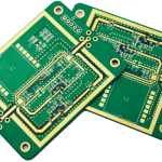
Bare Board Test: Electrical Methods Compared
A bare board is tested electrically before any component is mounted, and the test looks for two conditions: a net that should be continuous but is broken, and an isolation failure between two nets that should not touch. The test is performed on every panel by most suppliers, because a defect found on the bare board can be repaired or the panel scrapped at a fraction of the cost of finding the same defect after the assembly has been built.
This article explains what is measured, how a fixture and a flying probe differ, how the choice is made, and how the test program itself is verified.
What Is Tested
Continuity is measured by applying a current between two points of the same net and comparing the voltage with a threshold. The threshold is chosen to distinguish a good trace from a nearly broken one, and it is typically a few ohms up to some tens of ohms depending on the net and on the probes. Isolation is measured by applying a voltage between two nets and confirming that the leakage is below a limit, which is usually in the megaohm range, and the test voltage is chosen to be high enough to reveal a weak path without damaging a thin dielectric.
Some suppliers also perform a high voltage test between selected nets, which verifies the spacing that a high voltage design requires and reveals a conductive path that a low voltage measurement would not find. The coverage of the test is defined by the netlist, so the completeness of the test depends on the completeness of the data rather than on the machine.
The panel is tested rather than the individual board, which changes what a failure means. A short between two nets on one board of a panel is a defect in that board, while a plating problem may affect every board on the panel, and the repair decision therefore depends on the pattern rather than on the single result. Some suppliers mark the failing position on the panel and repair it, others scrap the affected board and let the rest continue, and the choice is written into the purchase specification rather than decided by the operator.
The Fixture Method
A fixture carries a probe for every test point, mounted on a grid and wired to the tester, and it is built specifically for the product. The panel is clamped onto the fixture, the probes contact the test points, and every net is checked in a few seconds. The fixture is fast and repeatable, and its accuracy depends on the alignment of the probes with the pads, which is why the pad size, the grid, and the test point placement follow the rules described under pad design standards.
The cost and the lead time are the disadvantage. A fixture is a tooling item, it has to be designed and built before the first boards can be tested, and a change to the layout makes it obsolete. Where the pads are too small, too close together, or outside the grid, the fixture cannot be built at all, and the test has to move to a flying probe or the design has to change.
The Flying Probe Method
A flying probe carries two or more moving heads, each with a probe, and it steps between the test points under program control. There is no tooling, so the program is generated from the netlist and the design data, and a change to the layout is a change to the program rather than a new fixture. The pads can be smaller and the spacing tighter, because the probe is positioned optically rather than by a drilled grid.
The disadvantage is time. Every net is visited sequentially, so a board with a thousand nets takes minutes rather than seconds, and the cost per board is therefore dominated by the test time. The machines compensate with multiple heads operating in parallel and with an optimised path, but the method remains an order of magnitude slower than a fixture, which is why it is used for prototypes, for low volume production, and for the panels of a new design before tooling is committed.
Choosing Between Them
The decision is mostly economic. Where the volume is high, the fixture cost is amortised over many panels and the shorter test time reduces the cost per unit further. Where the volume is low or the design is still changing, the flying probe avoids tooling that would have to be rebuilt, and it is also the answer for a prototype that has to be tested before the volume is known.
The geometry constrains the choice as well. A fine pitch design with small pads and a dense net count may not be compatible with a fixture grid, and a design with test points only on one side and at a generous pitch is well suited to one. Some suppliers run the flying probe first and then build a fixture when the design is frozen, which is a reasonable sequence for a product with a long life.
Verifying The Test Program
The program is only as good as its source. A netlist that is incomplete or that contains an error produces a test that verifies the wrong thing, so the netlist should be extracted from the same database that produces the artwork and the fabrication data. A known good board and a known bad board are then used to confirm that the program passes the good one and fails the bad one, and the bad board should carry both an open and a short so that both measurements are exercised.
The false call rate is the practical measure of a program. A probe that contacts a pad intermittently produces a failure that disappears on re-test, and a pad with a thin oxide or a residue produces the same symptom. The analysis of re-tests identifies those cases and leads to a change in the probe, the pad, or the cleaning, and the escape analysis, in which a board that passed the test fails later, points to a threshold that is too loose or to a net that the test does not cover. The acceptance framework is described under PCB design quality characteristics, and the fabrication sequence under PCB design and fabrication.
Process Control and Verification
On a design of this kind, continuity is the item that decides how the rest of the board is arranged. Where the requirement is not written down, the shop supplies its own default, and the default is chosen for the process rather than for the design. The measurements that matter are the repeatable ones: conductor width and spacing, annular ring, finished hole size, plating thickness and surface finish are all verifiable on a coupon that travels with the panel.
Process Control and Verification
On a design of this kind, continuity is the item that decides how the rest of the board is arranged. Where the requirement is not written down, the shop supplies its own default, and the default is chosen for the process rather than for the design. The measurements that matter are the repeatable ones: conductor width and spacing, annular ring, finished hole size, plating thickness and surface finish are all verifiable on a coupon that travels with the panel.
FAQ
Is a bare board test performed on every panel? By most suppliers, yes, because the cost of finding an open or a short before assembly is a fraction of the cost afterwards. The exceptions are usually low cost commercial panels where the specification does not require it.
Can a flying probe replace a fixture for volume production? It can, but the test time per board is much higher, so the cost per unit usually favours a fixture once the volume is sufficient to amortise the tooling.
What is the most common cause of a false failure? Poor contact at a probe, which is usually caused by a small pad, a residue on the pad, or a worn probe. It shows up as a failure that disappears when the same board is tested again.