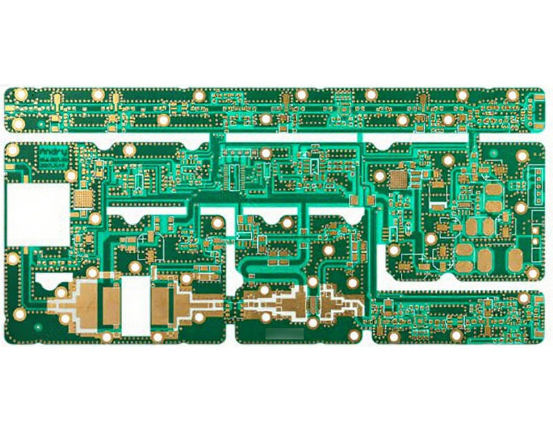
Conformal Coating Masking And Keepout Design
Conformal coating is applied after assembly to protect the board from moisture, contamination and electrochemical migration, and the coating has to be kept away from the features that must remain accessible or that cannot tolerate it. That is the masking requirement, and it is a layout decision as much as a process one, because the coated area and the masked area are defined by the component placement and by the copper pattern rather than by the spray booth.
This article describes what has to remain uncoated, how the masking is done, what the keepout rules are, and how the result is inspected.
What Has To Stay Uncoated
Four groups of features are normally excluded. Connectors and any surface that a mating part has to touch, because coating on a contact surface raises the contact resistance. Test points and programming pads, because a probe has to penetrate to the copper and a coated pad either blocks the probe or is damaged by it. Mechanical interfaces such as screw holes, standoffs and board edges that fit into a groove. And any component that the coating supplier states is incompatible, which includes some relays, some sensors and most optical devices.
Two further areas are usually excluded for process reasons. A component that has to be reworked should be surrounded by a small uncoated margin so that the coating can be cut and peeled without lifting it from its neighbours. And the area around a large thermal pad or a heatsink is often left uncoated so that the coating does not insulate the surface that has to reject heat.

How The Masking Is Done
The traditional method is a peelable mask, a latex or silicone compound brushed or dispensed over the areas to be protected and pulled off after the coating has cured. It is flexible enough to be applied by hand on a low volume product and accurate enough to define a line, and its weakness is that it can leave residue or lift a coating edge when it is removed.
The alternative is a dispensed mask, applied by the same machine that applies the coating, or a cap and plug set for connectors. Tapes are used on flat areas and around edges. Each method leaves a different edge: a tape leaves a sharp line, a peelable mask leaves a slightly ragged one, and a dispensed mask leaves a defined boundary that matches the machine’s accuracy. The choice should match the tolerance that the design actually needs rather than the best available.
Keepout Rules Around Components
The coating has to reach the surfaces that need protection and must not bridge between features that have to remain separate. A coating that bridges two adjacent pads has created a leakage path rather than removing one, and a coating that wicks into a connector body can prevent the mating part from seating. The keepout therefore has two parts: a distance to keep the coating away from the excluded feature, and a distance to make sure the coating fully covers what it is meant to cover.
Component height matters as well. A tall component shadows the area behind it in the direction of the spray, and a component with a small gap underneath can be bridged by the coating, which then traps flux residue. The shadowing is reduced by applying the coating from several directions and by choosing a material with a low viscosity, while the trap under the part is avoided by leaving a defined gap or by filling it deliberately.
Coverage, Thickness And Adhesion
The coating has to be continuous over the surfaces that need it and thick enough to withstand the environment. A typical acrylic coating is applied at 25 to 75 microns, and a silicone or polyurethane at a similar figure, with the thickness measured on a coupon that is coated with the same program. Thickness over the top of a component is not the same as thickness in the shadow beside it, and the thin region is where the protection fails.
Adhesion is what keeps the coating in place, and it depends on the cleanliness of the board rather than on the material. Flux residue, mask residue and fingerprints all reduce adhesion, and a coating that lifts from one area will allow moisture to travel along the interface underneath it. Where the coating is used together with a potting compound or a dispensed adhesive, the materials have to be compatible, and the combinations are discussed under potting, dispensing and adhesives and under conformal coating and board protection.
Rules To Write Down
The coated and uncoated areas belong on the fabrication or assembly drawing as a layer, not in a note. A layer can be checked automatically against the component placement, while a note has to be interpreted. The layer should define the boundary of the coating, the areas that are masked, and the keepout distance from each excluded feature, so that the shop and the designer are working to the same geometry.
The component clearance rules that the placement itself needs are described under manufacturable design guidelines. Where the coating requirement is added late to a design that was not laid out for it, the usual outcome is that a connector or a test point ends up inside the coated area, and the remedy is a rework operation that costs more than the layout change would have.
Verification
Verification is visual and dimensional. A black light is used with a coating that contains a fluorescent tracer, which makes the coverage visible and the thin areas obvious, and the same inspection finds the bridges and the areas that were masked by mistake. The thickness is measured on a coupon or with an eddy current gauge on the board, and the adhesion is checked by a cross hatch or a peel test on a sample.
The functional check is on the finished product. A coated board that fails a humidity or a salt spray test is usually showing a failure at the edge of a masked area, at a connector or under a component where the coating did not reach. Locating the failure on the drawing rather than on the board is what turns the test result into an improvement in the next revision.
Process Control and Verification
On a design of this kind, conformal coating is the item that decides how the rest of the board is arranged. A stack-up that is drawn rather than described removes most of the ambiguity from a quotation, and it lets the fabricator price the board against the dielectric and copper weights that will actually be used. Where the requirement is not written down, the shop supplies its own default, and the default is chosen for the process rather than for the design.
FAQ
Can the coating be applied over connectors? It should not be. Coating on a contact surface increases resistance and can prevent the mating part from seating, and the masking is a normal part of the process rather than an exception.
How much clearance should the mask have around a component? Enough for the coating to be cut and peeled without disturbing the part, commonly 1 to 2 millimetres, and the figure belongs on the drawing rather than in a work instruction.
Does the coating have to cover the whole board? No. Selective coating is common, and the areas that are left bare are chosen for access and for the components that cannot tolerate the material. What matters is that the boundary is defined and repeatable.