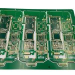
Depanel Routing And Tab Design For Assemblies
A depanel operation separates finished boards from the panel they were assembled in, and the way that separation is arranged is decided at the design stage. The panel carries the boards through printing, placement, reflow and test, and it has to hold them rigidly enough for those steps while still allowing each board to be removed without damage.
This article covers why panels exist, how routing tabs and v-score lines are dimensioned, what the separation step does to the assembly, and how edge quality is specified.
Why Boards Are Panelised
Assembly equipment handles panels, not individual boards. A panel of a standard size can be gripped on the conveyor, printed in one pass and placed in a single programme, and the machine time per board falls as the panel grows. Small boards in particular are impractical to run singly because they are too small for the conveyor rails and too light for the placement machine to hold repeatably.
Panelisation adds two things that the design must accommodate. The first is a border, a strip of material at the panel edges where the conveyor and the tooling holes engage, which is discarded after assembly. The second is a method of holding each board inside the panel and then releasing it. That method is the routing tab or the v-score line, and it is the part of the panel that determines whether separation damages the assembly. The outline and fixing requirements the panel is built around are described under board outline and mounting design.
Routing Tabs And Their Geometry
A routing tab is a short bridge of material left between the board and the panel after the outline has been milled. The mill follows the board outline and leaves tabs at intervals, and the board is removed later by cutting, snapping or breaking the tabs. Tab width is a compromise between rigidity during assembly and the force needed to break it: wide tabs hold the board firmly and require more force, narrow tabs break easily and let the board move during placement and reflow.
The tab should also be positioned where it does no harm. A tab placed on a straight edge, away from any component and away from a high stress region, is the safe arrangement. A tab placed near a corner where the board will be clamped, or on an edge that will be inserted into a connector, leaves a burr in the worst possible place. A common refinement is a perforated tab, a row of small drilled holes along the cut line that concentrates the break and leaves a cleaner edge with less delamination. The general rules covering slots and edges are treated under PCB slot and edge routing rules.

V-Score And Its Limits
A v-score is a pair of shallow grooves cut into both faces of the panel along the line where the boards will separate. The remaining material between the grooves is a web that breaks cleanly when the board is bent, and the process is fast, cheap and produces a straight edge with no burr and no dust. The grooves are cut with a saw whose angle and depth are controlled, and the depth sets both the strength of the web and the cleanliness of the break.
The limitation is geometric. A v-score can only be cut in a straight line all the way across the panel, so it cannot follow a curved or interrupted outline, and it cannot enclose a board on all four sides unless the panel is divided into rows and columns. It also consumes material and requires clearance on both faces, so a component placed too close to the score line will be damaged by the saw or by the breaking operation. Where these limits are reached, the design reverts to routing tabs, and a panel often uses both: v-score between boards in a row and routing tabs at the outer edge.
How Separation Loads The Assembly
Every separation method applies a load to the board at a moment when the board is fully populated with components. A snap or a bend puts the whole assembly into bending, and the strain is transmitted to solder joints, particularly to the joints of large components whose bodies are stiff. This is why depanel is one of the recognised causes of a cracked joint or a cracked ceramic capacitor on a board that passed every earlier test.
The remedy is to control both the method and the fixture. A cut with a router or a laser applies the least force to the assembly, a cutting tool with a support beneath the board applies less than a hand snap, and a bend that is applied only across the score line with the board supported either side applies less than a bend applied to the board itself. Whichever method is used, the separation should be done before the assembly is flexed by any other operation, and the fixtures that hold the board during it should support it directly under the line being broken. The way the separation step fits into the sequence of operations is part of the wider picture in how layout decisions affect production.

Edge Quality And Its Consequences
The edge left by a router is a milled surface with visible tool marks; the edge left by a v-score break is a clean line with a slight bevel; the edge left by a snap tab may have burrs and delamination. The consequence depends on what the edge will do in service. An edge that will slide into a card guide should be free of burrs and of protruding glass fibres. An edge that will be handled repeatedly should have no rough material that can injure an operator or shed particles. An edge near a conductor should have no delamination that exposes the copper.
Where the edge matters, the drawing specifies it. A general requirement is stated as a maximum burr height and a maximum protrusion, with the router path, the bit wear and the depth of the v-score all controlled to meet it. Delamination is the more serious defect and it is the harder one to see, because the material separates below the surface and appears only as a whitened band along the edge in a cross section or under magnification.
Specifying The Panel
The panel drawing should give the panel dimensions, the board positions, the border width, the tooling hole positions, the tab width and locations, and the method of separation. If v-score is used, the drawing gives the groove depth and the remaining web thickness. If tabs are used, it gives the tab width, the number of tabs and whether they are perforated. It also states which side the components are on, because that decides where the panel can be supported and where a cut can be made safely.
Two further numbers belong on the drawing. The first is the minimum distance from a component body to any separation line, which protects the component from the tool and from the break. The second is the minimum distance from a conductor to the board edge, which protects the copper from the burr and from the mechanical damage at the edge. Both are properties of the design rather than of the panel, and both are cheapest to satisfy when they are decided at layout rather than after the first panel is built. The complete set of fabrication driven constraints is collected under design guidelines for manufacturability.
FAQ
Which method damages the assembly least? A routed or laser cut separation applies the least force, because nothing is bent. A hand snap applies the most and should be avoided on densely populated boards, particularly where ceramic capacitors are used.
Can a v-score be used on a board with a curved edge? No. A v-score is cut in a straight line across the full panel, so it cannot follow a curve or stop part way. Curved or interrupted outlines need routing tabs.
Does the panel affect the board outline tolerance? It does, because the separation step and the panel’s own movement during processing both contribute to the final edge position. Where the outline is critical, the tolerance should be agreed with the fabricator as a finished board requirement.