Interconnect Stress Testing of PCB Vias and Plated Holes
An interconnect stress test passes a current through a chain of vias to heat them, then cools them, and repeats the cycle while measuring the resistance of the chain. The resistance rises as a barrel begins to crack, and the test stops when the change exceeds a defined limit. It is one of the few methods that measures the reliability of a plated hole directly rather than inferring it from a section, and it does so in hours rather than in weeks.
What the Test Measures
The test measures the electrical continuity of a daisy chain built from vias and the traces that connect them. Because the chain is in series, a change in any single barrel shows up in the total resistance, and the measurement is sensitive enough to detect a crack that has not yet opened the circuit.
The property being evaluated is the ability of the plated hole to survive thermal cycling, which is the failure mode that matters most in service. A board that passes the test has demonstrated that its barrels can accommodate the expansion difference between the copper and the laminate over the number of cycles applied.
How the Test Works
A current is passed through the chain, heating it by resistive dissipation, and the temperature is monitored from the change in resistance itself. When the target temperature is reached the current is reduced, and the specimen cools towards the ambient or towards a forced cool condition. The cycle then repeats automatically.
Because the specimen heats itself, the test does not need an oven, and the thermal profile is applied directly to the copper that is being evaluated. That is what makes the method faster than an oven based test and what makes it representative of the thermal load that a via experiences in service.
Test Coupons and Specimens
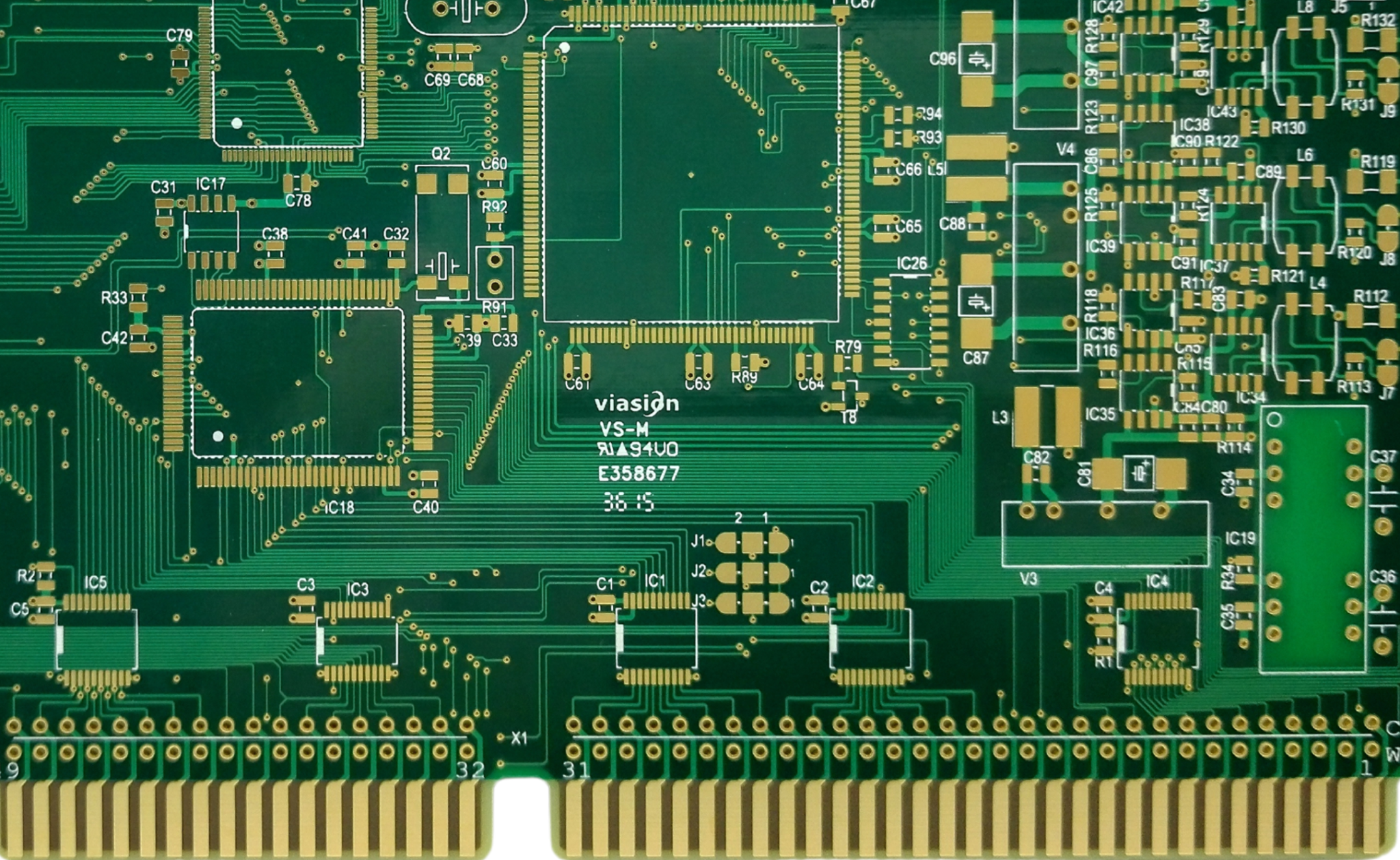
The specimen is a coupon built with the production process, containing a chain of vias that are representative of the product. The via size, the plating thickness, the laminate and the aspect ratio should all match the board being qualified, or the result describes the coupon rather than the product.
The coupon is normally placed on the panel at a defined position so that it experiences the same process conditions as the product. Its position matters, because plating thickness and registration vary across a panel, and a coupon from the centre is not equivalent to one from the edge. The design of such coupons is described in the guide to the PCB test coupon.
Cycle Conditions and Limits
The two parameters of the cycle are the temperature excursion and the dwell at each extreme. A larger excursion produces more strain per cycle, and a longer dwell allows the material to reach its full expansion, so both affect the number of cycles a specimen survives.
The conditions should be chosen to represent the product, or to represent a standard that the customer requires. Where the requirement is a number of cycles to failure under a defined condition, the same condition has to be used for every comparison, because results from different conditions cannot be placed on the same chart.
Reading the Resistance Curve
The result is a curve of resistance against cycle number. It typically shows an initial period in which the resistance changes slightly as the plating anneals, followed by a long period of stability and then a rise as cracks begin to form and accumulate.
The shape of the rise is informative. A gradual rise indicates a distributed cracking process, while a sudden step indicates a single barrel that has failed completely. The same data therefore describes both the reliability of the population and the behaviour of the weakest specimen, and both are useful.
Failure Criteria
The failure criterion is usually a percentage increase in resistance over the initial value, with limits commonly quoted between ten and twenty percent. The criterion should be defined before the test, because the number of cycles recorded depends entirely on the threshold that was chosen.
Where a product has a very low resistance chain, the same percentage represents a smaller absolute change and the measurement resolution becomes a limitation. The criterion should therefore be stated as an absolute value as well, and the measurement equipment should be capable of resolving it.
Comparison with Other Tests
Thermal cycling in an oven and thermal shock testing produce similar information but on a slower timescale and with a different thermal profile. A microsection shows the condition of the barrel at one moment rather than its behaviour over time, and it is destructive in a way that the stress test is not.
The methods complement each other. A section taken after a stress test shows exactly where the cracks began, which is the information needed to correct the process, while the stress test itself shows how many cycles the board can take. The structure of the barrel being evaluated is described in the guide to hole copper.
Interpreting Results for Design
The number of cycles to failure depends on the design as well as on the process. A small via with a thick, ductile plating survives more cycles than a large via with a thin deposit, and a lower expansion laminate reduces the strain on the barrel.
That means the result should be used comparatively, against a baseline that is known to be acceptable, rather than as an absolute prediction of field life. The comparison is what identifies a process that has drifted, and the design parameters that influence the result are discussed in the guide to aspect ratio.
Qualification and Records
The test is normally used to qualify a process, a material or a change, rather than to inspect production. A new laminate, a change in the plating chemistry, a different drill or a new lamination cycle all warrant a stress test, and the result should be compared with the baseline that was established for the product.
The records should include the coupon design, the process conditions, the cycle parameters, the failure criterion and the number of cycles at failure for each specimen. Several specimens are needed to characterise the population, and a single test result should be treated as an indication rather than as a conclusion.
Additional Considerations for This Build
Practical attention to resistance measurement pays for itself here, because it decides whether the finished board behaves as the drawing intended. Where the requirement is not stated on the fabrication drawing or in the assembly notes, the shop has to assume a default, and that default is rarely the value the design was simulated with. Stating resistance measurement explicitly, together with the tolerance that applies, removes the assumption and keeps the result predictable from batch to batch.
Deliberate attention to via reliability pays for itself here, because it decides whether the finished board behaves as the drawing intended. Where the requirement is not stated on the fabrication drawing or in the assembly notes, the shop has to assume a default, and that default is rarely the value the design was simulated with. Stating via reliability explicitly, together with the tolerance that applies, removes the assumption and keeps the result predictable from batch to batch.
Process Control and Verification
On a design of this kind, thermal cycle is the item that decides how the rest of the board is arranged. Where a value sits close to a process limit, the drawing should say so, since the shop can then open the process window rather than working to a nominal figure that carries no tolerance. A stack-up that is drawn rather than described removes most of the ambiguity from a quotation, and it lets the fabricator price the board against the dielectric and copper weights that will actually be used.
FAQ
How many cycles should a board survive? The number depends on the product, on the excursion and on the coupon design, so it must be compared against a baseline rather than against a universal figure. A result that is consistent with previous builds of the same design is the useful benchmark.
What causes the resistance to rise? Cracking of the plated copper in the barrel, usually in the middle of the hole or at the corner where the barrel meets the surface pad. As the crack grows, the conducting cross section falls and the resistance rises in proportion.
Can the test be used on a finished board? It is normally applied to a dedicated coupon, because the test requires a chain of vias with accessible measurement points. Coupons built on the production panel give the same process history and are the standard approach.