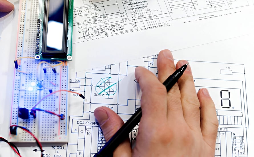
Copper Weight Selection For PCB Layers
Copper weight is the thickness of the copper foil on a layer, expressed in ounces per square foot. One ounce corresponds to about thirty five micrometres, and a standard board starts at half an ounce on the inner layers and one ounce on the outer. The choice is driven by current, by thermal spreading and by impedance, and it is limited by what the etching process can resolve.
This article covers how the weight is chosen, what it changes, and where it constrains the design.
Current And Thermal Reasons
The most direct reason to increase the copper weight is to carry more current. The resistance of a trace falls with its cross sectional area, so doubling the thickness halves the resistance and halves the temperature rise for the same current. On a power layer the effect is multiplied, because the plane carries the current over its whole area rather than through a single trace.
The second reason is thermal. Heavy copper spreads heat laterally, which reduces the temperature of a hot component and helps to move heat to a region where it can be dissipated. A design with a large power device and limited airflow often uses a heavier inner layer as a heat spreader, and the calculation that sizes a conductor for a given current and temperature rise is described under trace width and current calculation.
Effect On Etching
Thicker copper takes longer to etch, and the longer the etch the more undercut develops on the sides of the trace. The consequence is a practical minimum line width that rises with the copper weight: a fine line that is easy at half an ounce is difficult at two ounces, because the etch that clears the gaps removes too much from the sides of the traces.
The same effect limits the minimum gap. A design with heavy copper and fine gaps needs either a different process, such as a tenting and etching route with a different resist, or an adjustment of the artwork to compensate for the expected loss of width. Where the design mixes heavy copper for power and fine lines for signals on the same layer, the compromise is often poor, and the answer is to separate them onto different layers. The interaction of the copper with the fabrication process is described under PCB design and fabrication.
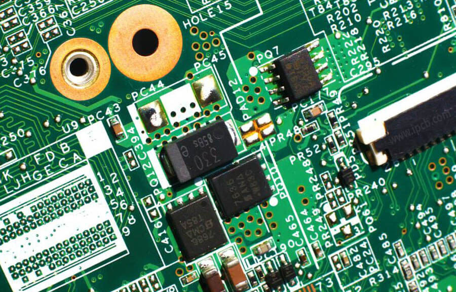
Impedance And Its Use
The copper thickness is one of the variables in the impedance of a transmission line, because the current does not flow uniformly through the conductor at high frequency: it concentrates near the surface. A thicker conductor reduces the resistance and therefore the loss, and it changes the impedance modestly. On a controlled impedance design the thickness is fixed by the stackup, and the width is adjusted to reach the target rather than the other way round.
The conductor loss matters most on a long line, where the attenuation accumulates. A backplane or a long interconnect benefits from thicker copper on the signal layers, not for the current but for the loss. Where the layer also has to carry power, the two requirements agree, and heavy copper is chosen for both reasons.
The Effect On Lamination And Weight
Heavy copper changes the lamination. The resin has to fill the spaces between the heavy traces, and a thick copper pattern leaves less volume for the resin than a thin one, so the dielectric over the copper is thinner and the resin has further to flow. A stack with heavy copper therefore needs a lamination cycle with more resin flow, and the designer should expect a different dielectric thickness over the copper than over the laminate.
The finished board is also heavier and stiffer. Neither is usually a problem, but a very heavy copper build is more difficult to handle and to keep flat, and the panel size may have to be reduced. The effect on the stack and on the balance of the layers is one of the reasons a heavy copper design should be agreed with the fabricator before it is committed. The arrangement of the layers that accommodates it is described under power plane splitting rules.

Choosing The Weight
The choice is normally made from the current and the thermal requirement, then checked against the minimum line width and the impedance. A digital board with a moderate current draw is comfortable at one ounce on the outer layers and half an ounce inside. A power board with several amperes per layer moves to two ounces or more, and accepts a coarser minimum line width as the price.
The decision should be made per layer rather than for the board as a whole, because the requirements differ. A ground plane that carries the return current of a high current load benefits from heavy copper, while a signal layer with fine routing does not. Mixed weights are common, and the only consequence is a separate lamination and etching step for each, which the fabricator handles.
Specifying And Verifying
The drawing should state the copper weight for each layer, the finished trace width and the impedance where it applies. The finished copper thickness on the outer layers includes the plating, which adds to the foil, so the specification should distinguish the base foil from the finished thickness. On an inner layer the foil thickness is the finished thickness apart from the oxide.
Verification is by a microsection across a trace, which shows the thickness and the profile, and by a weight measurement on a test coupon, which gives the average thickness over a known area. The section is the more informative of the two for a fine line, because it shows the shape as well as the thickness. The measurement is normally taken from a coupon rather than from the product, since the section is destructive.
Additional Considerations for This Build
Practical attention to current capacity pays for itself here, because it decides whether the finished board behaves as the drawing intended. Where the requirement is not stated on the fabrication drawing or in the assembly notes, the shop has to assume a default, and that default is rarely the value the design was simulated with. Stating current capacity explicitly, together with the tolerance that applies, removes the assumption and keeps the result predictable from batch to batch.
Process Control and Verification
On a design of this kind, etching is the item that decides how the rest of the board is arranged. Keeping a sample from the panel turns a dispute into a measurement, because the same coupon can be re-examined by both parties without rebuilding the batch. Reviewing the design before the data is released is cheaper than correcting it after the panel is in the tank, because every step downstream inherits the decision made at the front end.
FAQ
Does heavier copper always carry more current? It carries more for the same temperature rise, because the resistance is lower. The gain is proportional to the thickness up to the point where the trace can no longer dissipate the heat.
Why can a heavy copper layer not have fine lines? Because the etch required to remove thick copper also removes material from the sides of the traces, so the minimum width rises with the thickness. The limit is a property of the process rather than of the design.
Is copper weight the same as finished thickness? Not on an outer layer, where plating adds to the foil. A one ounce foil with plating may finish at one and a half ounces or more, and the specification should say which figure it means.