Visual Inspection Criteria for Solder Joints in Assembly
Visual inspection is the oldest and the cheapest check on a solder joint, and it remains the first line of defence on most assembly lines. It is also the check that varies most between operators, because it depends on eyesight, on lighting and on judgment. Making it reliable is a matter of defining what is acceptable, providing a workstation that shows the joint clearly, and training the people who make the decision.
What Visual Inspection Can and Cannot See
Visual inspection can see the fillet around a lead, the presence of a bridge, the alignment of a component and the obvious damage that handling causes. Those are the faults that a customer notices first, and catching them at the bench is far cheaper than catching them after the product has been built and shipped.
It cannot see under a component, inside a ball grid array, or below a large thermal pad. Neither can it measure a wetting angle or the thickness of an intermetallic layer, so the assurance it provides is limited to the surfaces that happen to be visible from the angle the inspector is using. Everything else has to be covered by a method that can look through the assembly, which is where X-ray and the automated systems take over.
The Reference Standard and Its Use
Acceptance criteria are usually taken from a published standard that describes joint shapes, permitted conditions and the defects that require rejection. The standard is only a starting point, because the product may impose its own requirements for a high reliability assembly or for a particular environment.
The standard has to be available at the bench rather than in an office, with the clause that applies to the product identified in advance. An operator who has to remember the criteria under time pressure is an operator who will apply them differently from one shift to the next.
Lighting, Magnification and the Workstation
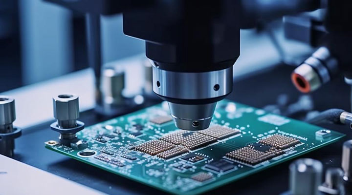
A joint is judged by the light reflected from it, so the lighting decides what can be seen at all. A diffused source placed at a low angle shows the profile of the fillet, while a bright source directly above flattens the image and hides the shape that matters most.
Magnification should be defined, because an inspector working at two times sees a different joint from one working at ten times. The station should also be arranged so that the board can be turned and supported and so that the operator can work for a full shift without the fatigue that comes from a fixed posture.
Reading a Fillet
A sound fillet has a concave surface that rises from the pad to the lead, with a low wetting angle and a surface that is smooth. That shape is a consequence of the alloy wetting both surfaces, so a fillet that is convex or that sits as a ball suggests the solder never wetted the pad properly.
Both the pad and the lead have to be considered on a through hole joint, because the fillet on the solder side and the solder in the barrel are separate features. A joint can look entirely correct from below and still be incomplete on the component side, which is why the barrel is checked by other means.
Wetting, Bridging and Insufficient Solder
Incomplete wetting appears as a joint that sits on the pad without spreading, sometimes with a visible gap or a dark line at the interface. Bridging appears as a continuous connection between adjacent conductors, and it may be a thin web that is easy to miss without the correct viewing angle.
Insufficient solder is the hardest of the three to judge, because the acceptable range depends on the joint type and on the product. A fillet that is too small still conducts, but it is more likely to crack under thermal cycling, which is why a minimum is specified rather than left to taste. Judging it consistently is one of the skills that separates an experienced inspector from a beginner, and it is also the condition that most often becomes a dispute with a customer.
Component Damage and Placement Faults
Visual inspection covers the component as well as the joint. Cracks in ceramic bodies, lifted leads, chipped terminations and marks left by handling are all visible, and several of them are more damaging than a poor joint because they cannot be repaired.
Placement faults belong to the same check. A part that is rotated, offset or reversed may still be soldered correctly, and only a visual or optical check will find it. An electrical test may catch a reversed diode, but it will not catch a part that has been placed in the wrong position and soldered perfectly. The check is therefore a complement to the electrical test rather than a substitute for it.
Operator Qualification and Consistency
The difference between two inspectors is the largest single source of variation in visual inspection. Qualification should include a test set of boards carrying known conditions, and the results should be compared with the reference rather than with the inspector’s own opinion of what looks right.
Recertification matters as much as the initial training, because eyesight and attention change over time. Periodic checks with the same test set show whether an inspector is drifting, and they give a supervisor a factual basis for retraining rather than an impression. The test set should include borderline conditions, because agreement on the obvious defects is easy and agreement on the marginal ones is what matters.
Recording and Trend Analysis
The value of inspection rises sharply when the results are recorded. A count of defects by type and by position on the board shows whether a problem is random or concentrated, and the concentration is usually the clue to its cause.
The records also feed the improvement cycle, and the defect categories used on them should match those in the solder defects and board failures reference. A defect that falls after a change to the stencil or the profile confirms that the change was beneficial, while one that rises after a change of paste or a new operator is worth investigating immediately.
Where Visual Inspection Sits in the Flow
Visual inspection is normally placed after reflow and after any touch up, but its position depends on the product. A board carrying expensive parts is often checked before the next process so that a defect can be corrected before more value is added to it.
It complements rather than replaces the automated methods. Optical inspection covers the surfaces at speed, X-ray covers the joints that cannot be seen, as the comparison of X-ray and optical inspection sets out, and the human inspector deals with the unusual conditions that no program anticipates. The relationship between those methods is described in the guide to automated optical inspection.
FAQ
Is visual inspection still necessary with AOI? It is, for conditions that the program does not classify and for boards inspected in small numbers. The two are complementary, and the visual check is also what validates the optical program in the first place.
What magnification should be used? Enough to resolve the smallest feature the criteria refer to, and the same figure should be used by everyone working on the product. A defined magnification is part of making the result repeatable.
Can a visual check find a cold joint? It can find the dull, grainy surface that a cold joint often has, but it cannot confirm the internal structure. A joint that looks suspect should be confirmed by a section or by another method rather than accepted on appearance, and the solderability tests are the usual next step.