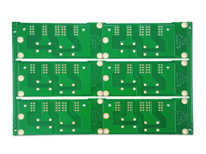
Flex Rigid Board Design Considerations
A flex rigid board is two constructions joined into one, and most of its difficulties come from the joint. The rigid sections behave like ordinary boards, the flexible sections behave like cables, and the transition between them carries the weaknesses of both.
Designing one well means deciding early where the bend will be, how many times it will bend and what supports the assembly on either side. Those three answers determine the stack up, the stiffeners and the layer arrangement more than any other requirement.
Where the Bend Goes
The flexible region should be placed where the movement is, and the rigid material should end well before the bend begins. A bend that starts at the edge of a rigid section concentrates stress in the laminate at the boundary, which is where most flex failures begin.
The bend radius should be specified with the stack up rather than chosen later, since a thinner flexible core allows a tighter radius. As a starting point the radius is kept several times the total flexible thickness, with the exact figure taken from the material supplier for the copper type in use.
Layer Arrangement
Copper on a flexible layer should be balanced, with similar amounts on both faces, so that the neutral axis stays near the middle of the material. Unbalanced copper moves the neutral axis and puts the conductors in tension or compression during every bend.
Conductors that must cross a bend should run perpendicular to the bend line where possible, since a trace parallel to the bend sees the highest strain. Where the routing requires a longitudinal trace, it should be wide and supported by adjacent copper rather than a thin isolated line.
Coverlay and Surface Protection
A flexible circuit is covered by a coverlay or a protective film rather than by solder mask, because mask cracks when it bends. The coverlay is bonded with an adhesive and has openings for the pads, and the openings have their own minimum size and tolerance.
The coverlay opening is usually larger than the pad, which is the opposite of the mask dam used on a rigid board. The reason is the adhesive flow: a tight opening traps adhesive on the pad and prevents soldering, so the design must leave room for the material to move.
Stiffeners and Their Attachment
A stiffener is a piece of rigid material bonded to the flexible section where a connector is mounted or where a component must be soldered. It provides the flatness and the mechanical support that the flexible material cannot, and it is specified by material, thickness and outline.
The stiffener outline has to be defined on the drawing with a tolerance, because it sets the boundary of the flexing region. A stiffener that extends into the bend area is worse than no stiffener at all, since it creates an abrupt change of stiffness at its edge.
Controlled Impedance on Flex
Controlled impedance is achievable on a flexible stack, and it depends on the dielectric thickness and the copper width in the same way as a rigid board. The difference is that the coverlay and the adhesive add to the effective dielectric, so a calculation done for a rigid board is not transferable.
The impedance should be verified with a coupon that includes the flexible construction, since the material properties change with the adhesive system and with the number of layers. This is the same discipline described for impedance discontinuity analysis.
Plated Through Holes and Bend Areas
Plated holes do not belong in a bend region, because the plating is brittle and a bend concentrates stress at the barrel. Where a via must be present, it should be in a rigid section or in a region that will not flex in service.
Similarly, the transition from a rigid to a flexible section should not contain a hole, because the change in stiffness at that point already concentrates stress. Keeping the transition clear of features is a simple rule that prevents a large share of field failures.
Component and Connector Placement
Components belong on the rigid sections, and connectors belong where the stiffener supports them. A connector mounted on an unsupported flexible section will eventually damage its joints, because every insertion applies force to a material that can deform.
Heavy components should be placed close to a stiffener or to a rigid area, since the mass of the part will be loaded by every movement of the assembly. Adhesives and staking are useful here for the reasons described for component bonding.
Assembly Handling
Flexible sections should be supported during printing and placement, which usually means a carrier or a pallet with a pocket that holds the assembly flat. Without support, a sagging flex region receives a different paste volume and a different placement height from the rest of the board.
Panel design should keep the flexible regions away from the rails of the conveyor, since a rail that grips a flexible section distorts it. The panel layout is therefore part of the flex design rather than a fabrication afterthought.
Testing and Inspection
Flexible assemblies are tested in the same way as rigid ones, with the addition of a bend test on a coupon to confirm that the construction survives the intended movement. The test should reproduce the radius and the number of cycles the product will see.
Inspection of a coverlay opening and of the bond line requires magnification, because the defects that matter are small delaminations at the edge. These are recorded with the same care as the parameters listed in manufacturing tolerances.
Documentation
The drawing must state the stack up with the flexible core material, the coverlay type, the stiffener material and the bend radius with its tolerance. Each of those is a decision that the fabricator cannot infer.
Where the product will be flexed in service, the drawing should also state the number of cycles expected, since that figure governs the material choice and the copper type. A flex design released without it has no basis for its own acceptance test.
Process Control and Verification
A first article check confirms that the process and the drawing agree on the points listed above, and that the coupon data supports the values used in the design.

Where a measurement falls outside the expected window, the sample is retained so that the cause can be established before the balance of the batch is released.
A first article check confirms that the process and the drawing agree on the points listed above, and that the coupon data supports the values used in the design.

Where a measurement falls outside the expected window, the sample is retained so that the cause can be established before the balance of the batch is released.
FAQ
Can a flex rigid board be reflowed like a rigid one? It can, provided the flexible sections are supported and the assembly is baked first, since polyimide absorbs moisture readily.
Is a stiffener always needed under a connector? Where the connector is inserted and removed repeatedly it is, because the joints cannot take the force on their own.
How tight can a bend be? The limit comes from the total flexible thickness and the copper type, and the supplier figure should be used rather than a general rule of thumb.
Should vias be allowed in the flexible section? They are acceptable away from the bend area, and they should never be placed where the material will flex in service.