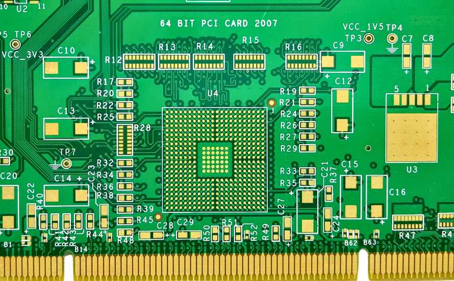
Via Stub and Back Drilling for High Speed Boards
A via that passes through a board leaves a stub below the layer where the signal turns, and at high frequency that stub behaves as a transmission line with an open end. It reflects energy back into the signal, and the reflection grows as the data rate rises.
Back drilling removes the unused portion of the barrel, which shortens the stub and moves the resonance above the frequencies the channel uses. It is one of the few fabrication operations that exists purely to improve signal integrity.
What a Stub Does to a Signal
The stub is a length of copper connected at one end and open at the other, so it resonates at a frequency determined by its length and the effective dielectric constant. At that frequency the channel loses energy that no equalisation can recover.
The first resonance of a typical stub falls within the band of a multi gigabit channel, which is why the technique became common as data rates increased. Below a few gigabits the effect is a minor loss, and above ten it can dominate the insertion loss budget.
How Back Drilling Is Done
A drill bit that is slightly larger than the finished via is used to remove the barrel from the side opposite the signal layer down to a controlled depth. The operation is performed after plating and before the outer finish, so the removed copper is not restored.
Depth control is the critical parameter. Too shallow and the stub remains, while too deep and the drill removes barrel from a layer that carries a connection, which creates an open circuit that is invisible.
Depth Tolerance and the Antipad
The depth is specified with a tolerance, and the tolerance has to be smaller than the distance between the intended stop and the nearest connected layer. That distance is what makes a thin board with closely spaced layers harder to back drill than a thick one.
The drill also requires an antipad around the via on the layers below, so that the bit does not cut into a plane. The antipad size is part of the design and should be checked before the data is released.
Stub Length and the Target
The remaining stub after drilling is what determines the resonance, and the target is usually expressed as a maximum stub length rather than as a depth. Values under ten thousandths of an inch are common for high speed channels, and the achievable figure depends on the depth tolerance.
The target should be derived from the channel: a shorter stub is better, and the point at which further reduction stops helping is when the resonance is above the highest significant harmonic.
Effect on the Via and the Barrel
Back drilling leaves a barrel that is open at one end and filled with the drill debris unless it is cleaned. The cleaning step is important, because residue in a blind barrel can outgas during assembly and contaminate a joint.
The remaining barrel still carries the signal, and its plating is unchanged, so the electrical behaviour of the used portion is not degraded by the operation.
Assembly Consequences
The back drilled side of the board has a counterbore at each via, and that recess affects how paste behaves if the via is in a pad. Where a back drilled via is under a component, the recess should be expected in the placement and the paste volume plan.
The surface is also less flat in the region of the counterbores, which can affect a stencil that has to seal across them. Designers usually keep back drilled vias away from fine pitch component areas for this reason.
Design Rules
The vias to be back drilled should be identified on the fabrication drawing with the side, the depth and the tolerance, and the antipads should be present on all the layers the bit will pass. Without the antipad the operation shorts a plane to the barrel or damages it.
The layer that carries the signal should be clearly marked, since the depth is measured from the opposite surface. Ambiguity about the reference side is a common source of scrap on this operation.
Cost and Yield Effects
Back drilling adds a drilling operation, a cleaning step and an inspection, so it increases cost and lead time. The yield effect is concentrated in the depth control, since an over-deep hole is not repairable.
Where the channel needs a short stub, the alternative is a blind or buried via built with sequential lamination, which costs more and constrains the stack up. Back drilling is often the cheaper of the two, which is why it remains in use.
Inspection
Inspection is by cross section on a coupon, measuring the remaining stub against the specification. A production board cannot be measured without being destroyed, so the coupon is the evidence.
The section should be taken through a representative via rather than a dedicated test hole, since the depth control depends on the local copper. The result is recorded with the same discipline as the other parameters in manufacturing tolerances.
Additional Considerations for This Build
Practical attention to via stub pays for itself here, because it decides whether the finished board behaves as the drawing intended. Where the requirement is not stated on the fabrication drawing or in the assembly notes, the shop has to assume a default, and that default is rarely the value the design was simulated with. Stating via stub explicitly, together with the tolerance that applies, removes the assumption and keeps the result predictable from batch to batch.
Process Control and Verification
On a design of this kind, back drilling is the item that decides how the rest of the board is arranged. Reviewing the design before the data is released is cheaper than correcting it after the panel is in the tank, because every step downstream inherits the decision made at the front end. Documenting the assumption is part of the design work, and a short note on the drawing prevents a question that would otherwise arrive a day later and cost a day of schedule.
The process window is set by the narrowest step in the flow, so an improvement anywhere else shows up as margin rather than as yield until that step is addressed. A short note on the drawing about handling, storage or packaging is often worth more than an extra decimal place on a tolerance.
Related reading: our fabrication notes, board quality and design release notes cover the same ground.
Process Control and Verification
On a design of this kind, back drilling is the item that decides how the rest of the board is arranged. Reviewing the design before the data is released is cheaper than correcting it after the panel is in the tank, because every step downstream inherits the decision made at the front end. Documenting the assumption is part of the design work, and a short note on the drawing prevents a question that would otherwise arrive a day later and cost a day of schedule.
A first article check confirms that the process and the drawing agree on the points listed above, and that the coupon data supports the values used in the design.
Where a measurement falls outside the expected window, the sample is retained so that the cause can be established before the balance of the batch is released.
A first article check confirms that the process and the drawing agree on the points listed above, and that the coupon data supports the values used in the design.
Where a measurement falls outside the expected window, the sample is retained so that the cause can be established before the balance of the batch is released.
FAQ
Does every high speed board need back drilling? Only where the stub resonance falls inside the band of interest, which is a calculation rather than a rule of thumb.
Can back drilling damage a via? It can if the depth is excessive or the antipad is missing, and both are design and process controls rather than random failures.
Is the counterbore a reliability problem? It is not, provided the barrel is cleaned and the surface is kept away from fine pitch assembly areas.
What is the alternative? A blind via from the opposite side, which removes the stub by construction and requires an additional lamination cycle.