Panel Utilization and Array Layout for PCB Cost
Two designs with the same circuit can differ by thirty percent in bare board cost because of how the boards are arranged on the production panel. Panel utilization is not a fabrication detail that the supplier should optimise alone, and it is not a decision that belongs only to assembly. It sits between the two, and getting it right means understanding what limits the panel, what the assembly line needs and how the two constraints interact.
What Sets Bare Board Cost
The fabrication price depends on panel area consumed, not on the area of one board. Material is bought in standard sheet sizes, and the number of boards that fit on a panel determines how much of that material ends up as product. Layer count, finish, tolerance and test add cost, but the first big lever is how efficiently the circuit uses the sheet.
The second lever is process capability. Very small boards are hard to handle and hard to register, so a panel that carries many small boards requires tighter tolerance and more careful process control, which raises the price per board even though the material utilisation looks excellent.
Panel Size and Equipment Compatibility
Fabrication equipment defines the maximum and minimum panel that can be processed. A panel that is too small cannot be clamped reliably and wastes capacity, while one that is too large cannot be imaged or drilled in a single pass. The practical range is usually defined by the supplier, and designs should be quoted in a panel size the supplier actually runs rather than in a size that only improves the arithmetic. The layer count also changes the calculation, because each additional layer adds its own registration and lamination risk, as the trade offs in choosing a layer count describe.
Assembly equipment imposes its own limits. Conveyors accept a range of widths, and the panel must be wide enough to be supported at the edges without the support intruding into the board area. Where a panel is narrow, the conveyor support may touch components, and where it is wide, the middle may sag during reflow.

Edge Rails and Spacing
Edge rail width is the first number to settle. The rail must be wide enough for the conveyor to grip and must extend fully along the two edges that run through the machine. A common starting point is a few millimetres on each side, increased when the panel is heavy or when the conveyor has a large gripping margin.
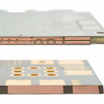
Spacing between boards has two roles. It provides the material that will be consumed by the separation process, and it gives the assembly line room for fiducials and for tooling. Routing, laser cutting and sawing all consume different amounts of material, so the spacing decision should follow the separation method rather than precede it. The design considerations for that interface are covered in breakaway tab design.
Array Layout and Orientation
Orientation is a cost decision as much as a mechanical one. Rotating a board by ninety degrees can change the number of units per panel significantly, and it also changes which edges carry the rail. The choice should be made on the actual board outline rather than on a rule of thumb, because the effect on yield is often larger than expected.
Component placement has to be considered at the same time. An array that improves material yield but requires a panel to run through the printer with a different alignment, or that leaves no room for fiducials on the rail, will cost more in assembly than it saves in material.
Fiducials, Tooling and Testability
Fiducials belong on the panel and on the individual board, and their position should be chosen so that both the printing and the placement machines can see them. Panel fiducials give global alignment, while board level fiducials allow local correction. Missing one of the two levels usually shows up as a placement offset that varies across the panel.
Tooling holes serve the printer, the placement machine and the test fixture, and they should be specified in the panel rather than in the board outline. Where a test fixture is planned, the panel must be able to carry it, which means the tooling positions and the board support points have to be agreed before the array is released. A checklist for the data package that records these decisions is described in PCB fabrication notes.
Depanel Method and Its Cost
The separation method determines how much spacing is needed and what the edges will look like. Routing leaves a clean edge but needs a wider gap, laser cutting produces almost no mechanical stress but costs per unit of cut length, and a saw requires a straight line and leaves a burr that must be controlled.
The method also affects the components. Manual breaking introduces bending, which is acceptable for a thin board with no heavy parts and unacceptable where a ceramic capacitor sits near the break line. The choice should be validated on a sample, and the resulting stress compared with the limits of the most sensitive part on the board.
Laminate Grade, Thickness and Panel Stiffness
The laminate grade affects how well a large panel behaves. A thin panel of a standard grade flexes easily, which makes handling and processing harder and reduces the usable array size. A thicker panel is more stable but consumes more material and weighs more, which changes how the conveyor and the magazine have to be set up.
High performance laminates behave differently again. They may be stiffer or more brittle than a standard grade, and their dimensional stability during lamination can differ enough to change how much spacing is needed between boards. The material properties that drive this behaviour are summarised in PCB laminate material properties, and they should be reviewed whenever a material change is proposed for cost reasons.
Balancing Yield Against Assembly Needs
The final decision is a compromise between material yield and assembly convenience. Maximising the number of boards per panel usually means thinner rails and smaller spacing, which reduces the handling margin and makes the assembly process less robust. Adding margin reduces the number of units per panel and raises the material cost per board.
The gopcb engineering team reviews the array against both cost models before release, because a panel that saves a small amount of laminate and costs a shift of assembly time is not a saving. Where the quantity is large, the review is worth repeating with the actual supplier price rather than with a rough estimate, since the cost structure changes with panel size.
FAQ
Who should decide the panel layout? The designer, with input from both the fabricator and the assembler. Deciding it in one of those places alone usually optimises one cost at the expense of the other.
Does a bigger panel always cost less per board? No. Larger panels are harder to process uniformly and can reduce yield, so the optimum is usually in the middle of the available range.
Can the panel layout be changed after the design is released? Yes, and it is often done for cost reasons, but the change must be revalidated for fiducials, tooling and separation stress.