Shielding Can Attachment and Rework
A metal can over a circuit is a mechanical part and an electrical one at the same time. It shields the components underneath from external fields and stops the circuit from radiating, and it has to be attached without damaging the very components it protects. Attachment and rework are therefore inseparable concerns, because a can that cannot be removed without destroying the board is a design liability.
Why a Shield Is Used
Shielding addresses both emission and immunity. A grounded metal enclosure around a circuit reduces the field that escapes and the field that reaches the components, and it also controls coupling between two circuits that would otherwise interact. The effectiveness depends on the enclosure being continuous and on its connection to a quiet reference.
Where the requirement is modest, a ferrite bead or a careful layout can achieve the same result at lower cost. Our notes on ferrite bead selection and on immunity in mixed signal design describe where a shield is necessary and where it is an expensive substitute for layout work.
Frame and Lid Configurations
A two piece shield has a frame soldered to the board and a lid that clips onto it. The frame carries the mechanical and electrical connection, and the lid can be removed for inspection or rework. This is the configuration that supports serviceability and it is the most common choice for assemblies that may need repair.
A one piece can is soldered directly to the board. It costs less and gives slightly better shielding, but removing it requires heating the whole perimeter, which puts every component inside at risk. Where a one piece part is used, the design should assume that the assembly is scrap if a component inside fails.
Attachment by Solder Paste
Paste printing on a shield frame footprint is difficult because the footprint is a continuous ring rather than a set of pads. A stencil can be made with a ring aperture, but the released volume is often uneven, and the ring tends to hold paste against the walls of the aperture rather than releasing it.
The usual alternative is dispensing. A dispenser lays a bead of paste along the ground trace, and the frame is placed into the wet paste and reflowed. Bead continuity is what matters: a gap in the bead leaves a mechanical and electrical discontinuity that may show up as a shielding failure or as a frame that lifts during handling.
Grounding and Contact Resistance
The frame has to connect to a ground that is quiet and low in impedance, and the connection should be continuous around the perimeter. A few tack points are not enough, because the shield behaves as an antenna at frequencies where the spacing between connections approaches a fraction of a wavelength.
Contact resistance also matters for the lid joint. A lid that relies on spring fingers needs enough finger pressure to break through any oxide on the frame, and the plating on both parts should be compatible. Mismatched finishes are a common cause of a shield that works when new and degrades in service.
Placement and Coplanarity
The frame is a large flat part, so coplanarity between the frame and the board determines whether the bead contacts the trace evenly. A frame that rocks seats on one side and leaves a gap on the other, which is the same problem discussed for fine pitch packages in our article on coplanarity.
Board flatness contributes as well. A board that bows during reflow lifts the frame in the middle of the bow, and the resulting open circuit is intermittent. Support under the board during reflow helps, and so does a frame design with a compliant foot.

Removing a Lid or Frame for Rework
Removing a lid is the easy case. The lid is heated with hot air along one edge and lifted with a tool, and because it is not bonded to the board the risk is limited to the frame and to nearby parts. A lid that has been soldered rather than clipped has to be treated like a one piece can.
Removing a frame is harder. The solder along the whole perimeter has to be molten at the same time, which means preheating the board from below and applying hot air from above, with a nozzle shaped to follow the ring. Pulling before the alloy is fully molten tears pads off the laminate and is the most common way this operation destroys a board.
Protecting Components During Rework
Components inside the shield see the heat that the rework applies, and they see it without the protection of a thermal path to a heatsink. Plastic parts such as connectors and electrolytic capacitors are the most vulnerable, and their temperature limits should set the rework window.
Local shielding with tape or a metal mask, a defined maximum temperature, and a dwell time measured rather than estimated all reduce the risk. Where the assembly is coated, the coating inside the shield also has to be considered, and the checks described in our article on conformal coating in assembly apply.
Verification After Attachment
Verification is mechanical and electrical. A visual check confirms bead continuity and the absence of solder balls, a pull or peel test on a sample confirms the joint strength, and a continuity measurement around the perimeter confirms the electrical connection. Where shielding performance is critical, a radiated emission measurement on a sample assembly is the only direct evidence.
Where a frame is soldered to a ground trace that also carries signals, the trace design has to allow the shield to be connected without creating a loop. The design review is the place to settle that, because it cannot be corrected at assembly.
Additional Considerations for This Build
Practical attention to shielding can pays for itself here, because it decides whether the finished board behaves as the drawing intended. Where the requirement is not stated on the fabrication drawing or in the assembly notes, the shop has to assume a default, and that default is rarely the value the design was simulated with. Stating shielding can explicitly, together with the tolerance that applies, removes the assumption and keeps the result predictable from batch to batch.
Deliberate attention to lid attachment pays for itself here, because it decides whether the finished board behaves as the drawing intended. Where the requirement is not stated on the fabrication drawing or in the assembly notes, the shop has to assume a default, and that default is rarely the value the design was simulated with. Stating lid attachment explicitly, together with the tolerance that applies, removes the assumption and keeps the result predictable from batch to batch.
Careful attention to solder paste dispense pays for itself here, because it decides whether the finished board behaves as the drawing intended. Where the requirement is not stated on the fabrication drawing or in the assembly notes, the shop has to assume a default, and that default is rarely the value the design was simulated with. Stating solder paste dispense explicitly, together with the tolerance that applies, removes the assumption and keeps the result predictable from batch to batch.
Consistent attention to emi shielding pays for itself here, because it decides whether the finished board behaves as the drawing intended. Where the requirement is not stated on the fabrication drawing or in the assembly notes, the shop has to assume a default, and that default is rarely the value the design was simulated with. Stating emi shielding explicitly, together with the tolerance that applies, removes the assumption and keeps the result predictable from batch to batch.
Process Control and Verification
On a design of this kind, emi shielding is the item that decides how the rest of the board is arranged. A short note on the drawing about handling, storage or packaging is often worth more than an extra decimal place on a tolerance. Where a value sits close to a process limit, the drawing should say so, since the shop can then open the process window rather than working to a nominal figure that carries no tolerance.
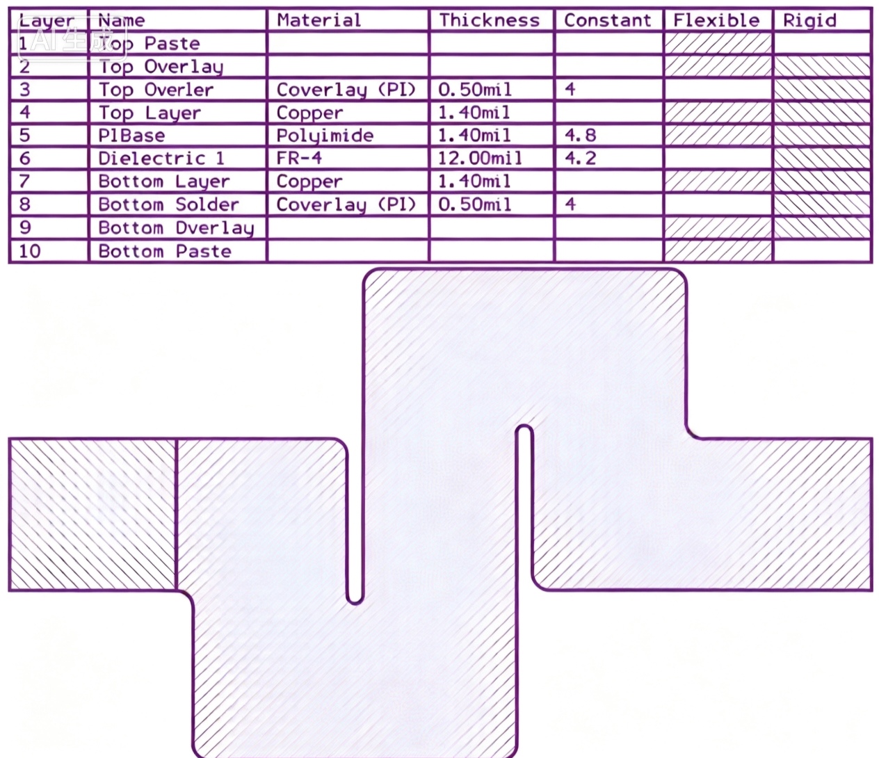
A stack-up that is drawn rather than described removes most of the ambiguity from a quotation, and it lets the fabricator price the board against the dielectric and copper weights that will actually be used.
FAQ
Can a shield be attached with conductive adhesive? Yes, and it avoids the thermal risk of soldering. The joint is less robust mechanically and has higher contact resistance, so it suits low stress applications rather than portable products.
Is a two piece shield worth the extra cost? Where the assembly may need repair, it usually is. A removable lid turns a scrap board into a rework job, and the difference in shielding performance is small.
How is the shield grounded? Through a continuous ring along the board perimeter, connected to a ground plane by vias placed close to the ring. A few discrete connections will not provide effective shielding at high frequency.