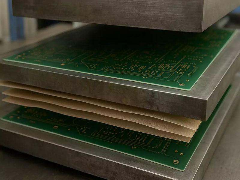
Layer to Layer Registration in Multilayer PCB
Every layer in a multilayer board has to line up with every other layer, and the alignment is built up from a series of steps that each contribute error. The total is what decides whether an inner layer pad still covers the hole after the drill has moved.
Where the Error Comes From
The artwork is imaged onto the panel, the layers are stacked and laminated, the panel is drilled, and each of those steps has a tolerance. Lamination adds a movement of its own, because the resin flows and the material shrinks as it cools.
The errors add rather than cancel, which is the reason the allowance is written as a total. Our layer assignment notes describe how the stack is arranged to keep the total manageable.
Tooling and Its Role
The layers are held in position by tooling, and the tooling is what converts the individual tolerances into a stack-up rather than a random arrangement. A tooling system with pins and slots that allow movement in one direction only is common, because it removes one degree of freedom at a time.
The tooling holes are drilled after lamination and the layers are registered to them, so the accuracy of those holes is a floor on the total. Our tooling and registration notes describe the system.
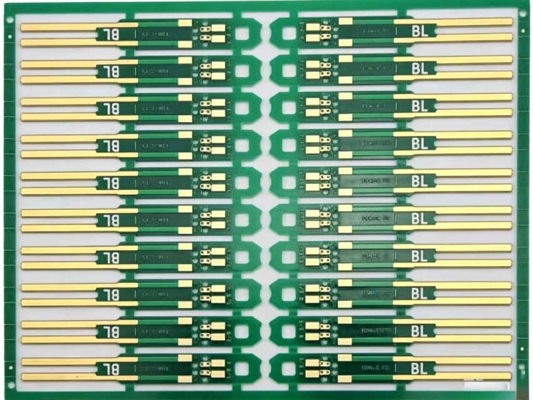
The material moves as it is processed, and the movement is not uniform in both directions. A panel that grows in one axis and shrinks in the other cannot be aligned by translation, and the correction is a scale factor applied to each layer.
The scale factor is measured on a target pattern and applied at imaging. Where the pattern is not measured, the board is aligned to an average that suits neither axis.
<img src="https://www.gopcba.com/wp-content/uploads/2026/06/IATF-16949.jpg" alt="Annular ring measured on a drilled coupon” />
The annular ring has to cover the registration error plus the drill tolerance plus the hole position tolerance. That total is the reason a small pad is difficult: the ring is what absorbs everything else.
A design that reduces the pad to gain routing density is trading that margin away, and the failure appears as a breakout rather than as a short. Our aspect ratio notes cover the related geometry of the hole itself.
Registration is measured by imaging a target on each layer and reading the offset after lamination, and by measuring the annular ring on a coupon after drilling. Both are routine and both are recorded per batch.
The coupon is the practical measurement because it can be sectioned without destroying a product board. Our board quality notes describe how the result is judged.
The rules that help are a larger pad on the layers furthest from the drill reference, a wider ring on a small hole, and a routing that keeps a fine pitch device away from the panel edge where the movement is larger.
Writing the requirement as a minimum annular ring rather than as a pad size lets the shop apply the rule to the whole design. A pad size that is quoted without the ring does not say what will remain after drilling.
Process Control and Verification
Keeping a sample from the panel turns a dispute into a measurement, because the same coupon can be re-examined by both parties without rebuilding the batch. Reviewing the design before the data is released is cheaper than correcting it after the panel is in the tank, because every step downstream inherits the decision made at the front end.
Documenting the assumption is part of the design work, and a short note on the drawing prevents a question that would otherwise arrive a day later and cost a day of schedule. The process window is set by the narrowest step in the flow, so an improvement anywhere else shows up as margin rather than as yield until that step is addressed.
A short note on the drawing about handling, storage or packaging is often worth more than an extra decimal place on a tolerance. Where a value sits close to a process limit, the drawing should say so, since the shop can then open the process window rather than working to a nominal figure that carries no tolerance.
A stack-up that is drawn rather than described removes most of the ambiguity from a quotation, and it lets the fabricator price the board against the dielectric and copper weights that will actually be used.
Can registration be corrected after lamination? No. The layers are bonded, and the correction is applied at imaging before the stack is built.
Does a thicker board register less well? The movement during lamination is larger and the drill has further to travel, so the total error is usually larger.
What does gopcb provide for registration? We provide a tooling system matched to the stack, scale factors measured on a target pattern and applied per layer, annular ring specified as a minimum, coupon measurement after drilling, and records per batch.
Checks Before Release
The checks that matter are the ones performed on the product rather than on a sample kept for the purpose, because a coupon that travels with the panel is the only evidence about that panel. Where a requirement can be measured, it should be measured at the point of manufacture and recorded against the board or the lot it applies to.
A parameter that is set once and never re verified drifts, and the drift is usually discovered by a defect rather than by the record. The tooling, the material and the profile form one system, and a change to any of them should be assessed against the other two before it is released.
Where the process window is narrow, the measurement resolution has to be better than the window, or the data cannot distinguish a good part from a marginal one.