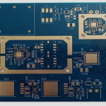
Board Edge Clearance and Panel Tooling
The panel edge carries the tooling that locates the panel in every machine it passes through, and the copper is kept back from that edge so that nothing touches a conductor. The width of the pullback is a fixed cost per panel and a design decision that is often made by default.
What the Edge Has to Provide
The edge provides a location reference and a handling zone. The tooling holes and slots are drilled or routed into the edge, and the conveyor and the fixtures grip the panel there rather than on the product area.
That means the edge has to be free of anything that a machine could damage and free of anything that could damage a machine. Our fabrication notes describe where the edge design is recorded.
Copper Pullback and Its Reasons
The pullback keeps copper away from the tooling so that a pin or a clamp cannot short two nets or scrape a conductor. It also keeps the plating out of the area that the router will cut, which reduces the burr on the finished edge.
The width is set by the tooling rather than by a general rule. A panel that is handled by a clamp needs more clearance than one that is located by a pin. Our board quality notes describe how the finished edge is judged.
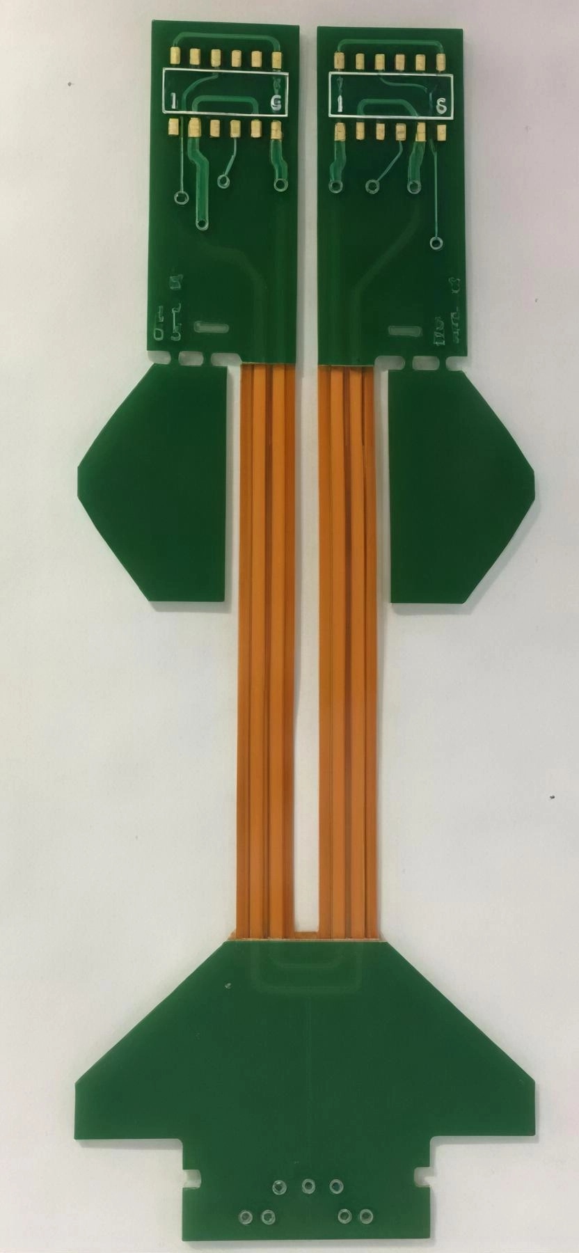
A round hole locates in both axes and a slot locates in one, and a combination of the two is common because it removes one degree of freedom at a time. That reduces the force needed and the wear on the tooling.
The choice also affects the registration through the process. A panel located on two round holes can be forced onto the tooling, and the resulting distortion shows up as a registration error rather than as a handling error. Our plating notes describe where a distortion of that kind appears.
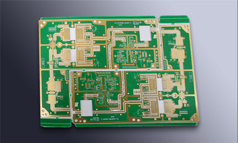
Where several products share the same equipment, the edge design can be standardised and the tooling reused. That removes a drawing from every new product and removes a class of tooling error.
The saving is in the setup and in the mistakes, both of which are larger than the copper that the pullback consumes. That is the reason a standard edge is common in a shop that runs many products.
The pullback and the tooling area come out of the panel area, so they reduce the number of boards that fit. On a small board the effect is proportionally larger, because the edge is fixed while the board shrinks.
That is worth knowing when an array is being designed. A small board that yields one row fewer on the panel costs more per unit than its area suggests. Our floor zoning notes describe the related question of how the panel is handled on the assembly line.
The tooling holes have a position tolerance and a size tolerance, and both are tighter than the general through hole requirement because the tooling depends on them. A tooling hole that is oversized allows the panel to move in the machine.
The finished size is what the tooling sees, so the figure on the drawing is the finished figure. A drawing that states the drill size leaves the plating allowance to the shop.
Acceptance and Its Evidence
Where an operation cannot be verified afterwards, it has to be controlled during the operation, and that control has to be visible in the record. Consumables have a life measured in cycles, and the replacement point should come from the measurement rather than from a failure.
The sequence of operations is part of the specification, because a different order produces a different result from the same steps. Where the process window is narrow, the measurement resolution has to be better than the window, or the data cannot distinguish a good part from a marginal one.
Where two operations share a tolerance, the allocation between them should be explicit rather than left to whichever is measured first. The narrowest feature on the board usually sets the process window for the whole product, so it deserves the closest attention at review.
Where a requirement can be measured, it should be measured at the point of manufacture and recorded against the board or the lot it applies to. Sampling is a compromise between cost and confidence, and the sample size should follow from the failure rate that has to be detected.
Where a decision is made by judgement, a boundary sample makes the judgement repeatable between operators and between shifts.
Verification and Records
A result that cannot be reproduced is not a result, and reproducibility should be demonstrated rather than assumed. The first article confirms that the setup matches the intent, and it is the cheapest point at which a wrong setup can still be corrected.
Where a process is at the edge of its capability, the margin should be bought deliberately rather than discovered during production.
Can the pullback be removed to gain area? It can where the tooling does not touch the edge, and the saving is usually smaller than the risk it creates.
Does the edge design change between products? It does unless the shop standardises it, which is the reason standardisation pays in a high mix environment.
What does gopcb provide for panel edges? We provide an edge design matched to the tooling in use, copper pullback stated as a figure, standardised edges where several products share equipment, tooling holes specified at the finished size with a position tolerance, and the utilisation effect reported with the array.
Checks Before Release
The checks that matter are the ones performed on the product rather than on a sample kept for the purpose, because a coupon that travels with the panel is the only evidence about that panel. A parameter that is set once and never re verified drifts, and the drift is usually discovered by a defect rather than by the record.
The tooling, the material and the profile form one system, and a change to any of them should be assessed against the other two before it is released. A record that identifies the operator, the date and the settings is worth more than a record that identifies only the result.