Microsection Preparation Technique for PCB Analysis
A microsection is the only way to see inside a plated hole, and the quality of the section decides whether the answer is real or an artefact of preparation. A badly ground sample can round a crack until it disappears, smear copper across an interface or pull plating away from the resin. This article covers the sequence that produces a section worth measuring.
What a Microsection Has to Show
A useful section shows the copper thickness on the surface and in the barrel, the plating distribution along the hole wall, the interface between plating and inner layer copper, and the condition of the resin behind the barrel. It also shows whether the barrel is cracked, voided or separated.
All of that depends on the plane of the cut. A section taken through the centre of a hole shows the true barrel, while one taken off centre shows an apparent thickness that is greater than reality and hides corner cracks.

Cutting through the hole axis is therefore the first requirement, and it should be verified by measuring the hole width in the image against the known drill diameter.
Sample Selection and Cutting
Samples should come from the positions that matter: the smallest hole, the largest hole, a hole near the panel edge and a hole in the centre. Each position represents a different combination of current density and chemistry movement during plating.
Cutting must not damage the feature. A coarse abrasive saw tears copper and opens artificial gaps, so a precision saw with a fine blade and coolant is used for the cut close to the hole, and the damage is then removed during grinding.
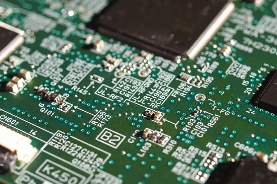
Samples are taken from coupons or from production boards with the customer’s agreement, and the location should be recorded so the result can be tied to a specific feature.
Mounting Methods and Edge Retention
The sample is encapsulated in a resin that supports the copper and the resin equally. A hard mount using a press and a thermosetting compound gives the best edge retention, while a cold mount is easier on heat sensitive samples but softer and more prone to rounding.
Edge retention is the property that matters. If the mount is softer than the copper, the copper smears across the hole during grinding, and the resulting image shows a continuous wall where a crack exists. Filler loaded mounting compounds are used specifically to match hardness.
Grinding and Polishing Sequence
The sequence runs from coarse to fine, with each step removing the damage introduced by the previous one. Grinding planes the sample and establishes the section plane, while polishing removes the scratches and produces a surface that can be examined at high magnification.
Time and force matter more than grit size alone. Excessive force at any step drives deformation deeper into the sample, so the following step has to remove more material, and the risk of rounding the hole edge increases with every extra minute of grinding.
Avoiding Artefacts: Smearing and Rounded Edges
Smearing is the most common artefact and the most dangerous, because it fills cracks and makes a defective board look acceptable. It appears as a smear of copper across the barrel or across the plating to resin interface, and it is usually visible as a change in colour or texture along the wall.
Rounding occurs when the sample edge is abraded more than the supported surface, so the hole edge becomes a curve rather than a corner. A rounded corner hides the corner crack that thermal shock testing is designed to reveal.
Etching for Grain and Intermetallic Definition
Etching uses a chemical to reveal boundaries and phases that polishing alone cannot show. A brief etch darkens the grain structure, separates the copper from the intermetallic layer and makes the interface visible for measurement.
It must be brief and controlled. Over-etching attacks the plating, pits the surface and changes the very thickness that is being measured, so the etchant, the concentration and the time are recorded as part of the method.
Measurement of Plating Thickness
Thickness is measured on the image, at defined positions rather than at one convenient point. Standard practice records surface copper, barrel copper at the top, middle and bottom of the hole, and the minimum value, because the minimum is what governs reliability.
The measurement should be tied to a calibration. A microscope with a stage micrometer or an image system with a scale bar both work, provided the calibration is checked, since an uncalibrated measurement can be wrong by a margin larger than the tolerance being judged.
Common Artefacts and Their Causes
Beyond smearing and rounding, common artefacts include pull-out of plating during grinding, cracks introduced by the cut and resin voids created by overheating during mounting. Each has a signature, and each is avoidable with the right consumable and the right force.
Where a section shows a defect, the usual practice is to prepare a second section from an adjacent hole before concluding anything. Reproducing the finding on a second sample separates a real process issue from a preparation artefact.
Reporting and Photography
The report should include the sample identity, the section plane, the magnification, the measurement positions and the calibration used, together with images that show the whole hole and the detail being measured. A photograph without a scale bar cannot be checked later.
gopcb files microsection results with the lot so that a later question can be answered from the original images. Using a consistent method for plating thickness and barrel condition also makes the results comparable with the quality data already held for earlier lots of the same product.
Points to Confirm at First Article
A change that is not recorded is a change that cannot be explained when the result moves, which is why the record is part of the process. The checks that matter are the ones performed on the product rather than on a sample kept for the purpose, because a coupon that travels with the panel is the only evidence about that panel.
Where an operation cannot be verified afterwards, it has to be controlled during the operation, and that control has to be visible in the record. Consumables have a life measured in cycles, and the replacement point should come from the measurement rather than from a failure.
Related reading: our fabrication notes, board quality and design release notes cover the same ground.
Documented Process Control
The cost of verification is small compared with the cost of a field failure, and it is paid at a point where the product can still be corrected. Where a requirement can be measured, it should be measured at the point of manufacture and recorded against the board or the lot it applies to.
FAQ
Why does my section show no cracks after thermal shock? Either the sample survived, or the crack was smeared during grinding or the section missed the hole axis. Prepare a second sample before drawing a conclusion.
How thick should barrel copper be? The requirement comes from the product class and the applicable standard, and it is the minimum value around the hole that matters rather than the average.
Should cold or hot mounting be used? Hot mounting with a hard compound gives better edge retention, which matters when copper must not smear across a crack. Cold mounting suits heat sensitive samples at the cost of a softer edge.