Drill Bit Life Management: Hit Count and Regrinding
A drill bit wears gradually, so the defect it causes appears as a trend rather than as a reject, and by the time the trend is visible the holes have already been produced. The control that works is a hit count established by measurement rather than a rule of thumb, supported by attention to the collet, the entry material and the chip load. This article covers the wear modes, the count and the process controls that surround them.
What Wears on a Drill
A carbide drill wears at the cutting edge, on the margin and at the chisel point, and each mode produces a different defect. Edge wear raises the drilling force and the temperature, margin wear enlarges the hole, and chisel wear pushes the hole off position relative to the artwork.
Because the wear is progressive, the first evidence is a drift in hole size or in the roughness of the wall rather than an obvious reject. That is why the control is a count rather than an inspection of the tool, and why the tool is replaced before the drift becomes a defect.
Hit Count and Its Basis
The hit count is the number of holes drilled between regrinds, and it is set by the hole diameter, the board thickness, the stack height, the copper weight and the material. A figure quoted without those parameters describes somebody else’s process rather than this one.
The count is established by drilling until a defined property moves outside its band and then setting the limit at a fraction of that figure. The property is usually hole size, wall roughness or position error, measured on a coupon rather than on production boards.
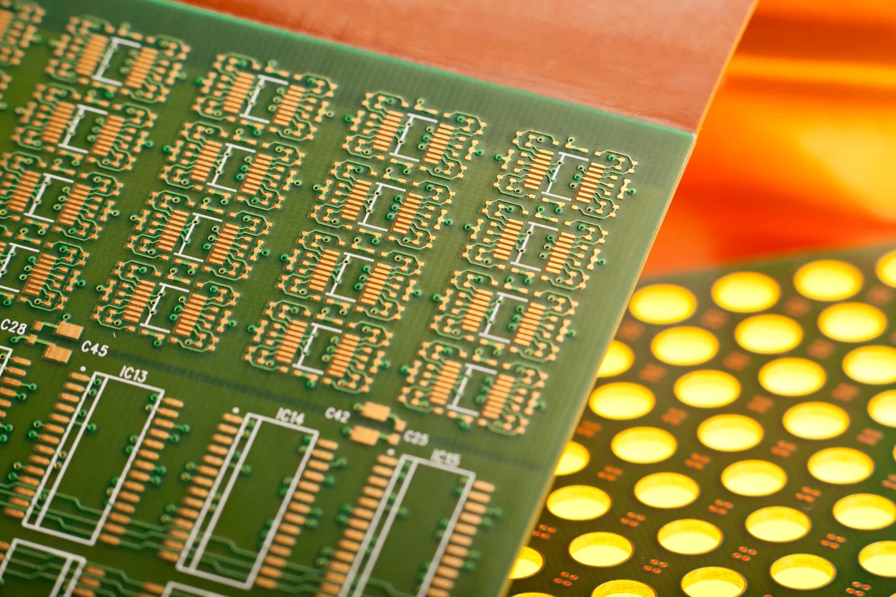
The measured property is chosen before the trial begins, because a trial that looks at several parameters at once produces a limit that cannot be explained later.
Regrinding and Its Effects
Regrinding restores the cutting edge, but it also changes the geometry of the bit: the diameter is reduced, the point angle is restored only approximately and the margin is re-cut. A reground drill is therefore a different tool from the one that was qualified.
The number of regrinds is limited, because each one removes material and reduces flute depth, which changes chip evacuation. A drill that has been reground several times cuts hotter and produces more smear, and the effect appears in the desmear load rather than at the drill.
Detecting Wear from the Product
Hole size drift is the most sensitive indicator, because a worn margin cuts a hole larger than the drill and the difference grows with the count. Measuring a sample of holes per spindle per shift gives a trend rather than an isolated reading.
Wall roughness and smear are the second indicators, and both are seen on a coupon section rather than on the production board. Where smear rises without a change in the desmear chemistry, the drill bit is the more likely cause than the process. The hole quality that matters downstream is described in our hole copper notes.
Spindle, Chuck and Runout
Runout at the drill tip produces the largest position deviation, and it comes from the spindle bearings, the collet and the shank of the drill. A worn collet holds the bit at a slight angle, which produces a hole that is both off position and tapered.
Runout is measured with a dial indicator on a test pin held in the collet, and it is re-checked after every collet change. A spindle whose runout has grown produces a pattern that follows the spindle across the panel, which makes the diagnosis straightforward.
Entry and Backup Materials
The entry material supports the copper and the top of the hole, and the backup controls the exit burr and the wall quality at the bottom. Both are consumables with their own life, and both are part of the drilling process rather than accessories.
An entry material used twice leaves a rough top edge, and a backup that is too thin lets the drill push material out of the exit side. The selection is made with the drill and the stack height rather than in isolation.

Entry and backup material are consumed at the same rate as the drills, so their cost belongs in the same comparison as the hit count rather than in general consumables.
Parameters and Their Effect on Wear
Spindle speed and feed per revolution set the chip load, and a chip load that is too low rubs the material instead of cutting it, which raises the temperature and accelerates wear. The correct chip load depends on the drill diameter and on the copper thickness it has to pass.
Withdrawal speed matters at the end of every cycle, because the drill has to clear the hole before the table moves on. A slow withdrawal leaves a cleaner wall and reduces the smear that the desmear step has to remove, at the cost of a small amount of cycle time.
Managing the Count in Production
The count is tracked per drill, and drills are identified by their position in the magazine rather than by appearance, because a worn and a new drill look the same at the machine. A drill that fails early is measured, and the holes it produced are checked as well as the tool.
A useful rule is that any drill reaching the limit is replaced rather than reground again, and the replaced drill is measured to confirm it was still inside tolerance. That measurement is what validates the limit over time, using the methods in our plating and sectioning notes.
Records and Continuous Improvement
The records worth keeping are the count at replacement, the measured hole size, the regrind history of the bit and the desmear load over the period. Together they show whether the limit is set correctly or is being reached long before the product needs it.
Where the count is consistently reached with the product still inside specification, the limit can be extended on evidence. Where drills fail early, the cause is usually the collet, the entry material or the chip load rather than the drill itself. The acceptance side of this is covered in our fabrication notes.
Hole wall quality is measured on a coupon by sectioning the holes and inspecting the plating for voids and the wall for smear. The section is taken from a panel drilled with the same parameters and the same bit count as production, so the result describes the process rather than a hand prepared sample.
Stack height changes the hit count, because a stack of three panels presents three times the drilling length and a different path for chip evacuation. Where a job moves from a single panel to a stack, the count is reduced before the run rather than after the first rejects.
Drill diameter tolerance from the supplier matters as well, because a batch at the high end of its range cuts a slightly larger hole and reaches the size limit sooner. Diameter is measured on a sample of bits at goods inwards rather than assumed from the certificate.
Where a job runs on more than one spindle, the count is tracked per spindle, because the spindle with the highest runout consumes its bits faster than the others. A single count across the machine hides that difference until the rejects appear.
FAQ
How many hits should a drill last? It depends on diameter, thickness, stack height and material, so the figure comes from a trial that measures a property rather than from a published average.
How many times can a drill be reground? The number is limited because each regrind reduces flute depth, and the practical limit is the point at which smear rises or the count falls sharply.
What causes a hole to drift off position? Runout at the tip, from the collet, the spindle or the shank, and it is recognised by the pattern following the spindle across the panel.