A PCB assembly line is where electronic designs are transformed into functional products. It is a critical part of modern electronics manufacturing, combining automation, precision equipment, engineering expertise, and quality control to turn bare printed circuit boards into reliable electronic assemblies.
From solder paste printing and component placement to reflow soldering, inspection, testing, and final packaging, each stage of a PCB assembly line contributes to the performance and reliability of the finished product.
Understanding how a PCB assembly line works is important for engineers, procurement teams, product developers, and manufacturers. Engineers can design PCBs with manufacturability in mind, procurement teams can evaluate suppliers more effectively, and product developers can create designs that transition smoothly from PCB prototyping and NPI to small-batch and volume production.
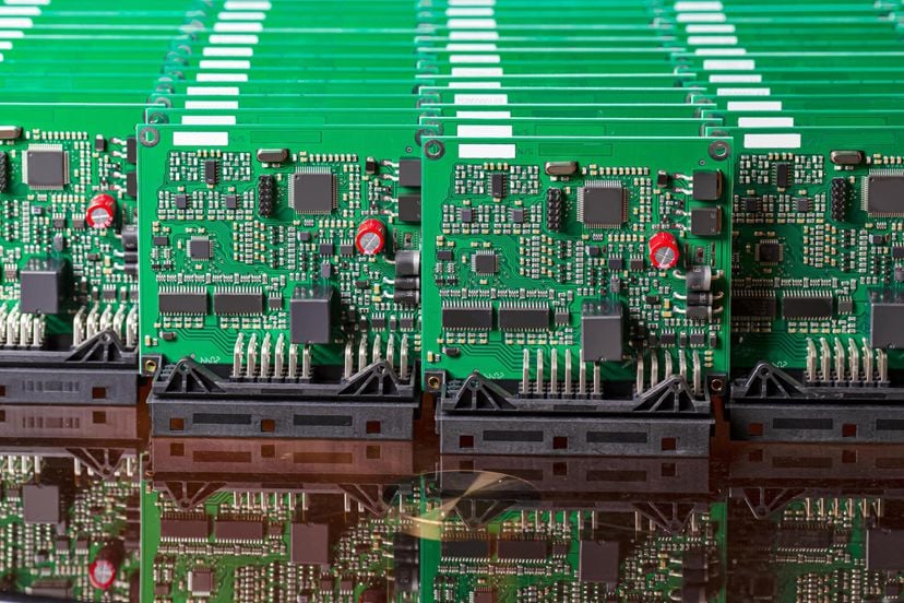
As an experienced PCB manufacturer and PCB assembly service provider, Kingda provides PCB prototype manufacturing, quick-turn PCB production, component sourcing, SMT assembly, THT assembly, PCB inspection, testing, and volume manufacturing solutions to support customers throughout the electronics manufacturing lifecycle.
What Is a PCB Assembly Line?
Definition and Purpose
A PCB assembly line is a coordinated manufacturing system used to transform a fabricated bare PCB into a completed printed circuit board assembly (PCBA).
During the assembly process, electronic components are mounted onto the PCB and electrically connected through soldering. Depending on the product design, the assembly process may involve surface mount technology (SMT), through-hole technology (THT), or a combination of both.
The main purpose of a PCB assembly line is to achieve:
- Accurate component placement
- Reliable solder joints
- Consistent production quality
- High manufacturing efficiency
- Repeatable production results
- Traceable quality control
- Scalable production from prototypes to mass production
It is important to distinguish PCB fabrication from PCB assembly.
PCB fabrication creates the physical circuit board. It includes processes such as copper lamination, circuit imaging, etching, drilling, plating, solder mask application, and surface finishing.
PCB assembly, in contrast, mounts electronic components onto the fabricated PCB and creates a functional electronic assembly.
A complete electronics manufacturing workflow may therefore look like:
PCB Design → DFM Review → PCB Fabrication → Component Sourcing → PCB Assembly → Inspection → Testing → Final Assembly → Shipment
Core Components of a PCB Assembly Line
A modern PCB assembly line consists of multiple machines and production stations working together.
The primary equipment typically includes:
Solder Paste Printer
A solder paste printer applies solder paste to the PCB pads through a precision stencil. This creates the solder foundation required for SMT component placement.
Pick-and-Place Machine
The pick-and-place machine automatically retrieves electronic components from reels, trays, or feeders and places them onto the corresponding PCB pads with high accuracy.
Reflow Oven
The reflow oven heats the PCB according to a controlled thermal profile, melting the solder paste and creating permanent solder joints.
Inspection Equipment
Inspection equipment such as SPI, AOI, and X-ray inspection systems identifies solder paste defects, component placement errors, soldering problems, and hidden solder joint defects.
THT and Soldering Equipment
For boards containing through-hole components, manufacturers may use manual insertion, automated insertion, wave soldering, or selective soldering.
Testing Equipment
Electrical and functional testing equipment verifies that the assembled PCB meets the required electrical and functional specifications.
Conveyor and Material Handling Systems
Conveyors and automated handling systems transfer PCBs between production stations while maintaining appropriate production flow and reducing unnecessary manual handling.
Together, these systems create a highly controlled manufacturing environment where each PCB can be assembled with consistent quality and efficiency.
Step-by-Step PCB Assembly Process
The exact PCB assembly process varies according to PCB structure, component types, product requirements, and production volume. However, a typical SMT assembly line follows a sequence similar to the one below.
Step 1 — Solder Paste Printing
The first major stage of an SMT PCB assembly line is solder paste printing.
A stainless-steel stencil is positioned accurately over the PCB. Solder paste is then applied across the stencil using a controlled squeegee system.
The stencil contains openings corresponding to the PCB’s solder pads. When the stencil is removed, the solder paste remains on the designated pads where components will later be placed.
The quality of solder paste printing has a significant impact on downstream soldering quality.
Important process parameters include:
- Stencil thickness
- Aperture dimensions
- Solder paste viscosity
- Printing speed
- Squeegee pressure
- PCB alignment
- Environmental conditions
For high-reliability PCB assembly, Solder Paste Inspection (SPI) can be performed after printing. SPI equipment measures solder paste characteristics such as volume, height, area, and alignment.
Proper control at this stage helps prevent defects such as insufficient solder, excessive solder, solder bridging, and component displacement.
Step 2 — Component Placement
After solder paste printing, the PCB moves to the pick-and-place machine.
The machine automatically picks electronic components from reels, trays, or other feeders and accurately places them onto the solder-pasted pads.
Typical SMT components include:
- Resistors
- Capacitors
- Diodes
- Transistors
- Integrated circuits
- Microcontrollers
- Sensors
- Connectors
- Power management devices
- RF components
Modern placement systems use high-speed vision technology to identify component orientation and position.
The placement program is generated from the customer’s PCB design and component placement data, ensuring that each component is installed at the correct location.
For prototype and low-volume production, some components may be placed manually when appropriate. However, automated placement is generally preferred for medium- and high-volume production because it provides better consistency, speed, and repeatability.
Step 3 — Reflow Soldering
Once all SMT components have been placed, the PCB enters the reflow soldering process.
The board travels through a reflow oven containing multiple temperature zones. The temperature is carefully controlled to ensure that the solder paste melts and forms reliable electrical and mechanical connections.
A typical reflow process includes four stages:
1. Preheat
The PCB temperature is gradually increased to minimize thermal shock and prepare the board for subsequent heating.
2. Soak
The temperature is stabilized to help equalize thermal conditions across the PCB and its components.
3. Reflow
The PCB reaches a temperature above the solder alloy’s melting point. The solder particles melt and form solder joints between the components and PCB pads.
4. Cooling
The board is cooled in a controlled manner to solidify the solder joints and establish their final mechanical and electrical properties.
Reflow profile optimization is particularly important for complex PCBs containing high-density components, large thermal masses, fine-pitch packages, or temperature-sensitive components.
Step 4 — Inspection and Quality Control
After reflow soldering, the PCB assembly undergoes inspection.
A combination of automated and manual inspection methods can be used depending on product requirements.
SPI — Solder Paste Inspection
SPI is generally performed after solder paste printing. It verifies whether solder paste has been deposited correctly before component placement.
SPI can identify:
- Insufficient solder paste
- Excessive solder paste
- Misaligned printing
- Inconsistent paste volume
- Missing paste
- Stencil-related printing defects
AOI — Automated Optical Inspection
Automated Optical Inspection (AOI) uses cameras and image-processing systems to inspect assembled PCBs.
AOI can detect:
- Missing components
- Incorrect components
- Component misalignment
- Polarity errors
- Solder bridges
- Insufficient solder
- Excessive solder
- Visible solder joint defects
AOI provides rapid and repeatable inspection, making it particularly useful for medium- and high-volume PCB assembly production.
X-Ray Inspection
X-ray inspection is used when solder joints cannot be adequately inspected from the surface.
It is especially useful for:
- BGA packages
- QFN packages
- Bottom-terminated components
- Hidden solder joints
- High-density PCB assemblies
X-ray inspection allows manufacturers to identify internal defects such as voiding, insufficient solder, bridging, and other hidden connection problems.
Manual Visual Inspection
Manual inspection remains useful for prototypes, engineering samples, low-volume production, and detailed verification.
Experienced inspectors can identify visible defects that may require additional investigation.
Using multiple inspection methods provides a more comprehensive PCB assembly quality control system.
Step 5 — Through-Hole Component Insertion
Not every PCB uses SMT components exclusively.
Some designs contain through-hole components, which have leads that pass through drilled holes in the PCB.
THT components are commonly used for:
- Connectors
- Large capacitors
- Transformers
- Relays
- Switches
- Power components
- Mechanically stressed components
Through-hole components provide strong mechanical connections and can be beneficial in applications where components experience mechanical stress, vibration, or higher electrical loads.
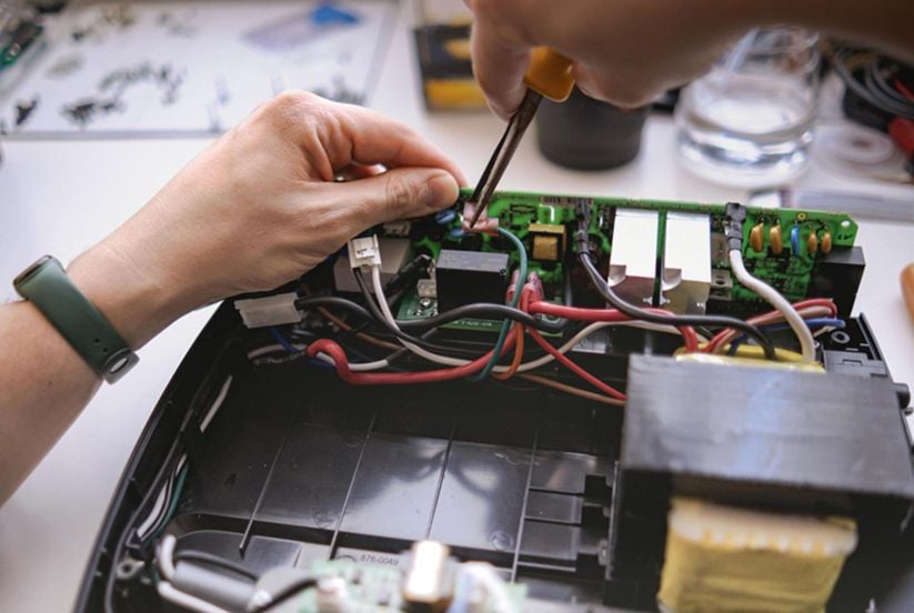
Depending on production volume and component characteristics, THT components can be inserted manually or with automated equipment.
Wave Soldering
Wave soldering is a common automated process for soldering through-hole components.
The PCB passes over a controlled wave of molten solder, allowing solder to contact the exposed component leads on the underside of the board.
Wave soldering is particularly effective for boards with a suitable THT component arrangement and relatively high production volume.
Selective Soldering
Selective soldering is useful for mixed-technology PCBs where only specific through-hole components need to be soldered.
Instead of exposing the entire underside of the board to a solder wave, selective soldering applies molten solder to specific locations.
This approach helps protect nearby SMT components and provides greater process control for complex assemblies.
Step 6 — Functional Testing
After assembly and inspection, the PCBA may undergo electrical and functional testing.
Testing methods depend on the complexity and requirements of the product.
In-Circuit Testing (ICT)
In-Circuit Testing (ICT) uses test points and electrical measurements to evaluate individual circuits, components, and connections.
ICT can help identify:
- Open circuits
- Short circuits
- Incorrect component values
- Certain component placement problems
- Electrical connection defects
ICT is particularly useful for products with stable designs and relatively high production volumes where dedicated test fixtures can be justified.
Flying Probe Testing
Flying probe testing uses movable test probes to access selected test points on the PCB.
Unlike traditional ICT, flying probe testing generally does not require a dedicated fixture, making it suitable for:
- PCB prototypes
- NPI
- Engineering samples
- Low-volume PCB assembly
- Products with frequent design changes
Functional Circuit Testing
Functional Circuit Testing (FCT) verifies whether the PCBA performs according to its intended operating conditions.
The test system may supply power and simulated signals while measuring parameters such as:
- Voltage
- Current
- Signal output
- Communication interfaces
- Sensor responses
- Power management
- System functions
Functional testing is especially important for products where electrical continuity alone does not guarantee correct operation.
Step 7 — Cleaning, Coating, and Final Processing
After soldering and testing, additional processes may be required depending on product specifications.
PCB Cleaning
Flux residues and other contaminants may remain on the PCB after soldering.
When cleaning is required, the appropriate cleaning method should be selected according to the solder paste, flux chemistry, components, PCB materials, and end-use environment.
Proper cleaning can help reduce the risk of contamination-related reliability problems.
Conformal Coating
For products exposed to moisture, dust, chemicals, or harsh environments, conformal coating may be applied to protect PCB assemblies.
Typical applications include:
- Automotive electronics
- Industrial controls
- Outdoor electronics
- Power electronics
- Aerospace and other demanding environments
The coating material and application method should be selected according to the product’s environmental and reliability requirements.
Step 8 — Final Inspection and Packaging
Before shipment, completed PCB assemblies undergo final quality verification.
The final inspection may include:
- Visual inspection
- Component verification
- Solder joint inspection
- Electrical testing
- Functional testing
- Label verification
- Packaging inspection
For sensitive electronic products, ESD-safe packaging and moisture protection may be required.
Manufacturers can also use barcode and lot tracking systems to maintain product traceability throughout production.
A robust traceability system records relevant manufacturing information and makes it easier to investigate quality issues, perform root-cause analysis, and manage after-sales support.
Key Equipment Used in a PCB Assembly Line
A professional PCB assembly line depends on the coordination of multiple machines. Each piece of equipment performs a specific function while contributing to overall production quality and efficiency.
Solder Paste Printer
The solder paste printer establishes the foundation for SMT soldering.
Modern printers can use automatic optical alignment to identify PCB fiducials and accurately position the stencil.
Important factors include:
- Printing accuracy
- Stencil alignment
- Squeegee pressure
- Printing speed
- Paste volume
- Stencil cleaning
Regular stencil cleaning and equipment calibration help maintain stable printing performance.
Pick-and-Place Machine
The pick-and-place machine is one of the most important pieces of equipment on an SMT production line.
It combines high-speed component placement with vision-based positioning technology.
Performance is commonly measured in components per hour (CPH), although actual production throughput depends on component mix, board complexity, feeder configuration, placement strategy, and machine setup.
Modern placement systems can handle a wide range of packages, from miniature passive components to larger ICs and connectors.
Reflow Oven
The reflow oven creates the solder joints that mechanically and electrically connect SMT components to the PCB.
A production reflow oven generally contains multiple heating and cooling zones, allowing manufacturers to develop a controlled thermal profile for each product.
The reflow process must consider:
- Solder alloy
- PCB thickness
- Component thermal limits
- Component density
- PCB material
- Thermal mass
- Conveyor speed
- Temperature distribution
A properly optimized reflow profile helps reduce soldering defects and improve long-term assembly reliability.
AOI Inspection System
An AOI system uses cameras and software to inspect PCB assemblies automatically.
It is commonly positioned after reflow soldering and may also be used at other stages depending on the manufacturing process.
AOI provides rapid inspection and helps identify production defects before boards move to subsequent stages.
X-Ray Inspection System
X-ray inspection provides visibility into solder joints that cannot be fully inspected optically.
It is especially important for advanced PCB assemblies containing BGA, QFN, and other hidden-joint packages.
SPI System
SPI equipment measures solder paste deposition immediately after stencil printing.
Because solder paste defects can create downstream soldering problems, identifying these issues early can significantly improve process control.
THT and Selective Soldering Equipment
For mixed-technology PCB assembly, additional equipment may include:
- THT insertion equipment
- Wave soldering machines
- Selective soldering systems
- Manual soldering stations
The appropriate equipment depends on PCB structure, component mix, production volume, and soldering requirements.
SMT vs. THT PCB Assembly Lines
SMT and THT assembly serve different manufacturing requirements.
| Feature | SMT Assembly | THT Assembly |
|---|---|---|
| Component mounting | Surface-mounted | Leads inserted through PCB holes |
| Automation | Highly automated | Manual or automated |
| Component size | Suitable for miniature components | Generally larger components |
| Assembly speed | High | Generally lower |
| PCB density | Excellent | More space may be required |
| Mechanical strength | Good | Excellent for many mechanically stressed components |
| Typical applications | Consumer electronics, communications, computing | Power electronics, connectors, industrial equipment |
| Soldering method | Reflow soldering | Wave/selective/manual soldering |
Surface Mount Technology
SMT assembly is widely used in modern electronics because it supports compact designs, high component density, automated manufacturing, and high production throughput.
A typical SMT line is:
Solder Paste Printing → SPI → Pick and Place → Reflow → AOI → X-Ray/Testing
Through-Hole Technology
THT assembly remains important for components that require strong mechanical connections, larger packages, or specific electrical characteristics.
A typical THT process is:
Component Insertion → Inspection → Wave/Selective Soldering → Inspection → Testing
Mixed Technology Assembly
Many electronic products require both SMT and THT components.
A typical mixed-technology workflow may be:
SMT Printing → SMT Placement → Reflow → THT Insertion → Selective/Wave Soldering → AOI/X-Ray → Electrical Testing → Functional Testing
The exact sequence depends on the PCB design and component arrangement.
Common Challenges in PCB Assembly Lines
Even highly automated PCB assembly lines can encounter process challenges. Effective process control is essential for maintaining high yield and reliable product performance.
Solder Bridging
Solder bridging occurs when solder unintentionally connects two adjacent conductive pads.
Common causes include:
- Excessive solder paste
- Incorrect stencil aperture design
- Fine-pitch component spacing
- Poor PCB alignment
- Improper reflow conditions
Tombstoning
Tombstoning occurs when one end of a small passive component lifts away from the PCB pad during reflow.
It can be influenced by:
- Uneven pad design
- Unequal solder paste volume
- Temperature differences
- Component placement
- PCB layout
Component Misalignment
Component displacement can occur during placement or reflow.
Proper fiducials, accurate placement programs, stable solder paste printing, and optimized reflow profiles help minimize this risk.
Equipment Calibration
Regular calibration and preventive maintenance are essential for:
- Solder paste printers
- Pick-and-place machines
- Reflow ovens
- AOI systems
- X-ray inspection equipment
- Testing systems
Equipment performance can gradually change over time, so scheduled maintenance helps maintain consistent production quality.
Supply Chain Challenges
Component availability can also affect PCB assembly production.
Obsolete components, long lead times, shortages, and unauthorized substitutions can create significant manufacturing risks.
A reliable PCB assembly manufacturer should therefore have effective component sourcing and supply chain management capabilities.
How Automation and AI Are Changing PCB Assembly Lines
The development of Industry 4.0 technologies is transforming traditional PCB assembly into increasingly connected and data-driven manufacturing systems.
Smart Factory Integration
Modern PCB assembly lines can connect production equipment through manufacturing execution systems and factory-level data platforms.
Production data may include:
- Machine operating status
- Placement data
- Soldering profiles
- Inspection results
- Production quantities
- Defect information
- Equipment maintenance records
This data enables manufacturers to monitor production in real time and identify process abnormalities more quickly.
AI-Assisted Inspection
AI and machine-learning technologies are increasingly being integrated into AOI and X-ray inspection.
AI-based systems can analyze large amounts of inspection data and identify recurring defect patterns.
Potential benefits include:
- Faster defect detection
- Improved inspection consistency
- Reduced false calls
- Better process analysis
- Faster root-cause identification
AI should complement, rather than replace, appropriate engineering controls and experienced quality personnel.
Predictive Maintenance
Connected equipment can also monitor machine conditions and identify potential maintenance issues before they cause major downtime.
Predictive maintenance can help manufacturers:
- Reduce unexpected equipment failures
- Improve equipment utilization
- Reduce production interruptions
- Extend equipment service life
- Improve overall production efficiency
How to Choose a PCB Assembly Manufacturer
Selecting the right PCB assembly manufacturer is an important decision for both engineering teams and procurement departments.
A capable supplier should offer more than basic component placement.
PCB Manufacturing Capability
Check whether the supplier can support the PCB technologies required for your product, including:
- Single-sided PCBs
- Double-sided PCBs
- Multilayer PCBs
- HDI PCBs
- Flexible PCBs
- Rigid-flex PCBs
- High-frequency PCBs
- Metal core PCBs
Assembly Capability
Evaluate whether the supplier can provide:
- SMT assembly
- THT assembly
- Mixed technology assembly
- Prototype PCB assembly
- Small-batch PCB assembly
- Volume PCB assembly
- Quick-turn PCB assembly
Engineering Support
A strong supplier should be able to review manufacturing data before production.
Important engineering services may include:
- DFM review
- DFA review
- BOM review
- Component availability analysis
- PCB manufacturability analysis
- Assembly optimization
- Test strategy development
Inspection and Testing
A professional PCB assembly supplier should have appropriate inspection and testing capabilities.
Depending on product requirements, these may include:
SPI → AOI → X-Ray → ICT/Flying Probe → Functional Testing → Final Inspection
Component Sourcing
Component procurement is another important factor.
A reliable supplier should have processes for managing component quality, availability, lead times, and approved substitutions.
Production Scalability
The ideal manufacturing partner should support the product throughout its development cycle:
PCB Prototype → NPI → Small-Batch Production → Volume Manufacturing
This reduces the need to repeatedly change suppliers as production volume increases.
Kingda PCB Assembly Line and Manufacturing Advantages
As an experienced PCB manufacturer and PCB assembly service provider, Kingda provides integrated manufacturing solutions for customers developing and producing electronic products.
Kingda’s services can cover the complete manufacturing workflow from PCB prototype manufacturing and quick-turn production to component sourcing, PCB assembly, inspection, testing, and volume production.
One-Stop PCB and PCBA Manufacturing
Kingda can integrate PCB fabrication and assembly services, helping customers simplify supplier management and improve communication between PCB manufacturing and assembly processes.
PCB Prototype and Quick-Turn Production
During the product development stage, fast PCB prototyping allows engineers to validate circuit designs and identify manufacturing issues before entering larger-scale production.
Kingda supports customers from prototype development through subsequent production stages.
SMT, THT, and Mixed Technology Assembly
Different electronic products require different assembly technologies.
Kingda provides support for:
- SMT PCB assembly
- THT PCB assembly
- Mixed technology PCB assembly
- Prototype PCB assembly
- Small-batch PCB assembly
- Volume PCB assembly
This allows the assembly process to be selected according to the actual product design and production requirements.
Engineering and DFM Support
Kingda can provide engineering feedback during the pre-production stage.
DFM and DFA reviews help identify potential manufacturing and assembly issues before production begins, reducing unnecessary rework and improving production efficiency.
Comprehensive Quality Control
Quality control can be integrated throughout the manufacturing process.
Depending on project requirements, inspection and testing may include:
SPI → AOI → X-Ray → Electrical Testing → Functional Testing → Final Inspection
This multi-stage approach helps identify defects early and maintain consistent product quality.
Component Sourcing Support
Kingda can support component procurement based on customer-approved BOMs.
Professional component sourcing helps customers manage:
- Component availability
- Lead times
- Approved alternatives
- Supply chain risks
- Production continuity
Prototype to Volume Production
One of Kingda’s key advantages is the ability to support different stages of product development and manufacturing.
The complete workflow can be summarized as:
PCB Design → DFM Engineering Review → PCB Prototype Manufacturing → PCB Assembly → Inspection & Testing → Design Optimization → Small-Batch Production → Volume Manufacturing
This integrated approach helps customers move from initial design validation to stable and scalable production more efficiently.
Conclusion
A modern PCB assembly line is a highly coordinated manufacturing system that combines precision equipment, automation, engineering expertise, inspection, and testing.
The typical process begins with solder paste printing, followed by SPI, component placement, reflow soldering, AOI, THT insertion, wave or selective soldering, electrical testing, functional testing, cleaning, final inspection, and packaging, depending on the product requirements.
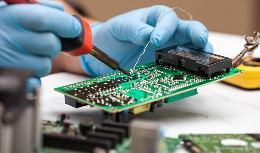
SMT provides high-speed, high-density automated assembly, while THT offers strong mechanical connections for components such as connectors, power devices, and large components. Many modern products therefore rely on mixed technology PCB assembly to combine the advantages of both technologies.
At the same time, automation, AI-assisted inspection, smart manufacturing, and digital traceability are making PCB assembly lines increasingly efficient and data-driven.
Choosing an experienced PCB assembly manufacturer is therefore essential for controlling quality, production costs, lead times, and manufacturing risks.
With capabilities covering PCB manufacturing, PCB prototyping, quick-turn PCB production, component sourcing, SMT assembly, THT assembly, mixed technology assembly, inspection, testing, and volume manufacturing, Kingda provides comprehensive PCB and PCBA solutions to support customers from initial design verification to reliable mass production.