Bad Mark: Key Checks Before Release
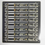
A bad mark is a signal that tells the placement machine a unit inside the panel has already failed and must be left empty. The mark is applied after the electrical test or the inspection step that found the fault, and it travels with the panel to the SMT line. Without a bad mark, the machine populates a board that will be scrapped anyway, and every component on it is lost with the panel.
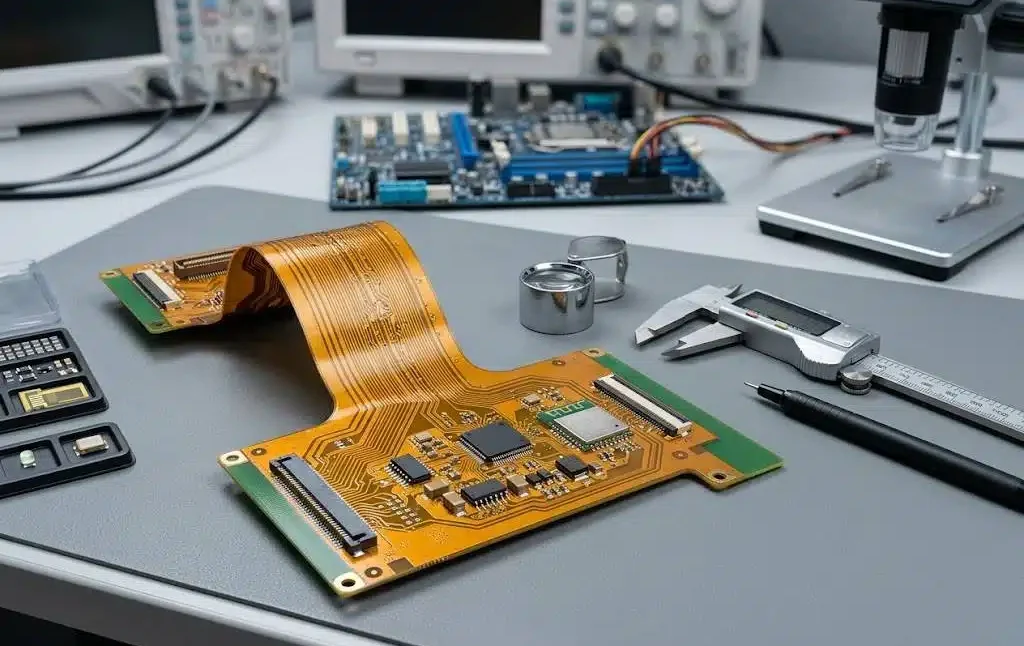
Bad mark handling is a process rather than a device. It starts with the test step that decides which units are good, continues through the panel map that the placement program reads, and ends with the sort that separates populated units from empty ones after depaneling. Each stage has to agree with the others, because a mark the machine cannot read is the same as no mark at all.
What a Bad Mark Signals to the Placement Line
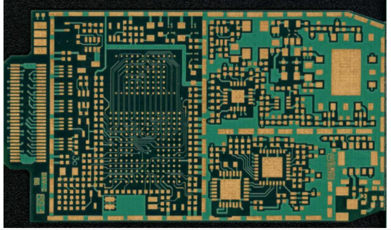
The bad mark carries one instruction: skip this unit. It is read at the start of the program, before the first component is placed, so the decision is made once for the whole run rather than unit by unit. The machine then follows its normal motion over the marked unit and places nothing, which keeps the placement rate and the conveyor timing unchanged.
The signal is deliberately simple because the environment is hostile to detail. A mark that has to be decoded slows the vision camera and adds a failure mode, while a mark that is a large, high-contrast feature can be found in a single image. Size, contrast and position decide whether the read succeeds, not the elegance of the design.
Where Bad Units Come From Before Placement
Most bad units are created in fabrication or by the electrical test that follows it. An open inner layer, a short between planes, a drilled hole outside tolerance or a plating defect the test detects are all reasons to mark a unit. The mark is applied after the fault is confirmed, not while it is still suspected.
Faults also appear after the first SMT pass. A unit that fails in-circuit test on a double-sided assembly cannot be marked for the first side, but it can be marked before the second side is populated. The rule should state which results justify a bad mark and which results call for rework instead, and the in-circuit test program is the right place to define that boundary.
Ink, Laser and Label Marks Compared
Ink marks are cheap and quick, and they are applied by hand or by a dispenser at the end of the test line. The risk is contrast, because a dot that lands on a bright copper plane can be hard to see and a dot that is too small is lost in the image. A black or white dot about two millimetres across works on most surfaces.
Laser marks are permanent and machine generated, so they match the panel map exactly, but they need a laser station and the marked surface can affect how solder mask covers it. Printed labels are the most readable option and the easiest to audit, yet a label can lift in the oven or be applied to the wrong unit. The IPC standards describe marking methods that survive assembly.
Teaching the Vision System to Read the Mark
The camera needs a stable reference before it can find a mark. That reference is the fiducial mark, which the machine locates first, and the bad mark is then searched inside a window defined relative to it. If the fiducial is found with an error, the search window moves with the error and a mark near the edge of the window disappears.
Teaching means setting the search window, the grey level threshold and the size limits so that the real mark passes and the noise does not. The test is then to run panels with marks in the worst positions, including a mark beside a bright connector pad, and to confirm the machine reports the unit as bad every time. The SMTA process library covers the same camera setup points.
Building the Panel Map for the Placement Program
The panel map is the list that ties a unit position in the array to a status. It is produced by the test system that found the fault, transferred to the SMT line as a machine-readable file, and loaded together with the placement program. The map has to use the same numbering as the stencil and the depanel drawing, or the machine will skip the wrong unit.
A panel map that is typed by hand is a defect waiting to happen. The transfer should be a file keyed to the panel serial number, and the operator should confirm the map on the screen before the first panel is placed. Where one line runs several products, the panel map should never be shared between programs, and the layout rules in panelization design rules should fix the numbering early.
Skipping Placement Without Losing Cycle Time
A skip is not a stop. The pick and place keeps its motion and its takt, so the units around the marked one are not disturbed and the conveyor does not need to be re-timed. Programs that pause on a marked unit give back the time that automation saved and push the following panels out of step.
The setting that matters most is the nozzle vacuum, which should be off over the marked unit so that no component is carried and dropped somewhere else. Where the machine supports it, the feeder advance can also be suppressed to save components. Both settings belong in the first article check, on a panel with a bad mark in the middle of the array.
Depaneling, Sorting and Salvage Rules
After depaneling the empty units travel with the populated ones and have to be separated. A marked unit that reaches the assembly pack becomes a missing component claim that takes time to resolve. The usual control is a sort station where the operator reads the panel map and places the empty units into a scrap bin, and the depaneling method decides how cleanly that separation can be made.
Salvage deserves an explicit rule. A unit marked for a small fault may still be worth populating by hand, particularly where the component cost is high. That decision should be made by the test engineer and recorded, because a hand populated unit that was never electrically retested is not the same product as the rest of the order.
Yield Records That Follow the Panel
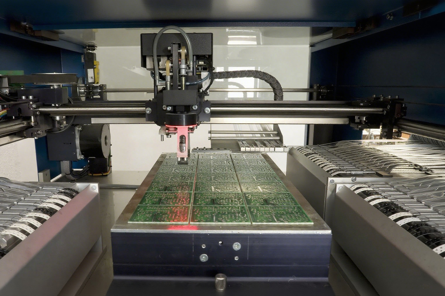
The panel map is also the yield record. It shows how many units were tested, how many failed and at which step, and it can be compared with the placement program log to confirm that every bad mark was honored. Without that comparison, a machine that misses marks produces scrap that looks like a placement error.
The record should be kept against the panel serial number, and the reason for each mark should be coded rather than written as free text. Codes can be counted, and counting is what turns a scrap pile into a Pareto chart that points at the process which needs attention. The traceability requirements for that record follow the same rules as any other build document.
FAQ
Can a bad mark be applied by hand at the placement machine? It can, but it should be the exception and it should be recorded. A hand applied mark has no link to the test record, so the panel map and the physical panel can disagree. Where hand marks are common, the test step is not marking consistently, and that is the problem to fix.
What happens when the machine misses a bad mark? It populates a unit that will be scrapped, and the component loss appears as a material variance rather than as a defect. The controls are a first article with marks in the worst positions and a periodic audit that compares the program log against the panel map.
Should the bad mark go on the unit or on the rail? On the unit, because the rail is removed before depaneling and a mark there cannot say which unit failed. A mark on the unit also survives the printer and the conveyor, which a mark on the rail may not, so the unit is the only place where the signal stays meaningful.