Board Depaneling Selection for Production Assembly
Separating finished boards from their panel looks like the simplest step in the process and is responsible for a surprising share of field failures. Board depaneling introduces mechanical stress, and the way that stress is applied decides whether a ceramic capacitor cracks, a solder joint fatigues or a board edge delaminates. Choosing a method is a design decision, not a purchasing one.
Why Depaneling Matters
Every separation method applies force to the panel. Scoring and breaking bends the material along a line, routing cuts it away with a rotating tool, and laser separation ablates it with heat. Each method concentrates stress in a different place, and the components nearest to that place carry the consequences.
The damage is often invisible. A cracked multilayer ceramic capacitor may measure correctly immediately after assembly and fail after the first thermal cycle in the field, because the crack propagates only when the board expands. This is why depaneling defects are among the most expensive to find, and why the method should be selected with the component layout in mind.
V-Score and Break Methods
V-scoring cuts a groove on both sides of the panel, leaving a thin web that is broken by hand or with a fixture. It is fast and inexpensive for straight edges and rectangular boards. The limitation is that the break applies a bending moment to the whole board, which stresses every component in line with the score.
Keep components away from the score line, and specify the web thickness deliberately: a thicker web gives a stronger panel but requires more force to break, transferring more energy into the board. Where the design has components close to the edge, use a fixture that supports the board on both sides of the break rather than breaking it by hand. Review the edge and mounting geometry with board outline and mounting design guidance before finalizing the panel.
Router Depaneling
Routing removes the material between boards with a small end mill, following the board contour. The cut is clean, the stress is localized to the cut path, and the method suits almost any outline, including curved edges and internal cutouts. For assemblies with delicate components, routing is usually the safest mechanical option.
Two details decide the result. The bit diameter and the feed rate must suit the material and the copper content, because a dull or overloaded bit generates heat and can smear the resin. The board must be rigidly supported during the cut, otherwise the vibration is transmitted into the assembly. Tab placement also matters: the remaining tabs must hold the board until the final cut, and then be removed without bending the assembly.
Laser Depaneling
Laser separation removes material with a focused beam, which means no mechanical contact and no tool wear. It is used for thin boards, for dense assemblies and for contours that a router cannot reach. The heat affected zone is small but not zero, and the cut edge is rougher than a routed edge, so the design must accept a slightly different edge finish.
The trade-offs are throughput and cost. Laser separation is slower per panel than routing and the equipment is more expensive, so it is usually reserved for designs where mechanical stress must be minimized or where the geometry makes routing impractical. Where it is used, confirm that the laminate’s decomposition products are extracted properly, since the process generates fumes that must not be allowed to condense on the assembly.
Edge Quality and Stress Limits
Edge quality affects both appearance and function. A routed edge shows tool marks; a scored edge shows the characteristic bevel; a laser cut edge may show a small heat affected zone and discoloration. For most products these are cosmetic, but where the board edge is a mating surface or a sealing face, the finish becomes a functional requirement.
Stress limits are more important. Define the maximum strain a component can tolerate, then choose the method and the fixture that stay below it. Ceramic capacitors and crystal resonators are the most sensitive; connectors and large packages are more tolerant. Place sensitive parts away from the separation path, and where that is impossible, specify a method with lower mechanical impact. Handle the finished boards with attention to PCB dimensional stability and expansion behaviour, since a board that has already been stressed will move more during later thermal cycles.
Tabs, Fiducials and Panel Design
Panel design determines how easily the boards can be separated without damage. Tabs should be placed so that the assembly remains supported through the process and the final separation does not require bending the board. Where v-scoring is used, the score line must not cross a connector or a tall component, because the break fixture needs a clear path.
Fiducials belong on each individual board as well as on the panel, so that the placement machine and the inspection system can align after separation. Add tooling holes for the depaneling fixture, and keep the panel border wide enough for the conveyor. Confirm the finished design against design guidelines for manufacturable boards before releasing the panel drawing.
Choosing a Method
Start from the components near the edge, then consider the outline, the volume and the equipment available. Rectangular boards with generous edge clearance suit scoring. Boards with delicate parts, curved outlines or internal cutouts suit routing. Thin, dense or unusually shaped boards may need laser separation. In each case the cost difference is small compared with the cost of a field failure.
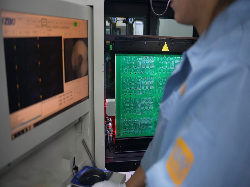
Test the choice on a pilot panel rather than in production. Separation a few hundred boards and inspect the sensitive components with a microscope or by acoustic microscopy before committing the whole program. gopcb assembles and separates panels for prototype and volume builds and can recommend the method that matches the panel design and the component mix.
Fixture and Support Design
The fixture that holds the panel during separation is as important as the method itself. A panel that is supported only at its edges flexes while the tool passes, and the flexing strain reaches the components. Support the board close to the cut line, and use a fixture whose surface is flat within a tolerance the assembly can tolerate.
For hand breaking, a simple support block is often enough, but it must be positioned so the operator applies pressure evenly rather than twisting the board. For automated separation, the fixture must locate the panel from tooling holes rather than from the outline, because the outline tolerance is larger and would allow the cut path to shift from panel to panel.
FAQ
Which method damages components least? Routing and laser separation apply the least mechanical stress, because the force is localized or absent. Scoring transmits a bending moment through the whole board and is therefore the most demanding on nearby components.
Can a scored edge be used as a mating surface? Usually not. The break leaves a bevel and a roughened edge that is difficult to control. Where the edge matters, rout the contour or machine it after separation.
Do I need fiducials on every board? Yes, when boards are inspected or placed after separation. Panel level fiducials alone are not visible to the machine once the panel has been divided, so each board needs its own reference.