Electrical Test Fixture Design: Probe Pitch and Grid Density
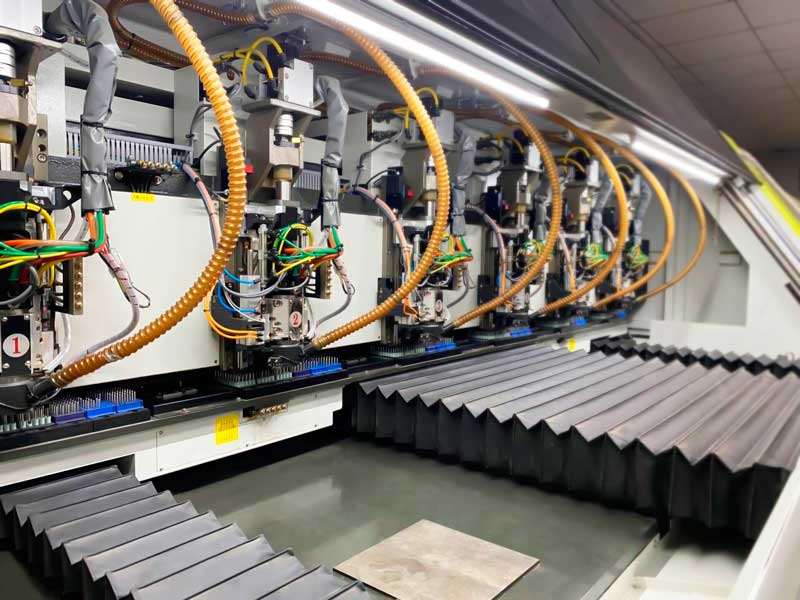
An electrical test fixture holds a bare board and presses a bed of probes onto its test points so that every net can be checked for continuity and isolation in a single pass. The fixture is where the electrical test either succeeds or becomes the bottleneck: a design that cannot be probed at the available pitch forces a slower method, and a fixture that is worn or misaligned produces false failures that cost more time than the defects it finds.
What the Fixture Has to Do
Three things are required. It has to position the board so that every probe lands on its target, it has to apply enough force for a reliable contact on each point without deforming the board, and it has to route the connections to the tester in a way that supports the measurements being made.
Positioning is normally done with tooling pins in the panel’s own holes, which means the fixture is built for a specific panel outline. The probe field is drilled to the coordinates of the test points, so a design change that moves a pad requires a new fixture rather than an adjustment.
Grid Density and Probe Pitch
The probe field is built on a grid, and the grid density determines the smallest pitch that can be probed. A 2.54 mm grid is the traditional standard; finer grids at 1.27 mm and below allow denser boards to be tested but demand tighter drilling tolerances and stiffer plates to keep the probes aligned.

Probe pitch and probe diameter are linked. A probe small enough for a 1.27 mm grid has a small spring and a small contact area, so the force it can apply is lower and the contact resistance higher. Where the board also has a thin plated surface, the two effects combine and produce intermittent readings that look like opens.
Test Coverage and Net Access
Coverage is the proportion of the nets that can be reached by a probe. It falls when a net has no accessible test point, when a test point is too close to a neighbouring feature, or when the pad is covered by solder mask. Adding test points costs board area, and the trade is made at design time rather than at the fixture.
A test point needs a defined minimum size, clearance from adjacent copper, and a via or pad that the probe tip cannot damage. Where the net is routed only through a via, the via should be left untented so that it can be probed, which is the opposite of what is wanted for other reasons and therefore worth deciding explicitly.
Probe Types, Wear and Contact Resistance
Probes are spring-loaded pins with a tip geometry chosen for the surface. A crown tip penetrates oxide and gives a consistent contact on a plated pad; a flat tip spreads the force and is used where the pad must not be marked. The spring force is a specification, and it falls as the spring ages and as the barrel collects debris.
Contact resistance rises as the tip wears and as the barrel fills with plating debris and flux residue. The rise is gradual, so the failures appear as intermittent false opens that move between boards. Measuring the resistance of a known short through the fixture at the start of each shift is the simple check that catches it.
Fixture Alignment and Registration
Alignment depends on the tooling pins, the plate that carries the probes and the board itself. A pin that is worn allows the board to rotate slightly, and the error grows with distance from the pin, so probes at the far corner of a large panel see the largest displacement. Two pins with a large separation give better angular control than two pins close together.
The panel outline also matters. Where the tooling holes are far from the probe field, the board can flex between the pins and the probes, and the flexure changes the contact force. A support plate under the board is the usual remedy, and it should be checked for flatness at the same interval as the probes.
Fixture Maintenance and Verification
Maintenance follows the wear items: probes, pins, springs and the support plate. Probes are replaced when their resistance rises above a threshold or when the tip is visibly worn, and the replacement interval should come from the measurement rather than from the calendar.
Verification is done with a known-good board wired as a fixture check, and with the resistance measurement described above. Recording the result per shift turns fixture condition into a trend, which is far more useful than discovering the problem when a customer lot reports a sudden rise in bare board electrical test failures.
Fixtured Test Versus Flying Probe
A fixture is fast per board but expensive to build, so it suits volume production of a stable design. A flying probe needs no fixture and can test a new design immediately, but it is much slower per board and its two or four probes limit how much can be measured in parallel.
The choice is usually made on volume and on how many design revisions are expected. For prototypes and small lots the flying probe is the practical answer; for volume the fixture pays for itself. Where the two are used together, the fixture handles the production and the flying probe handles the samples, and the fault threshold should be set the same way in both.
Effects of the Fixture on the Board
Probing leaves marks, and on a fine-pitch board the marks can be unacceptable on a pad that will later be soldered. The force applied by a bed of probes is also significant in total, and it can distort a thin panel enough to change the measurement or to crack a via barrel.
Both effects are controlled by the design of the test point and by the support plate. A test pad that is larger than the probe tip, separated from the solderable pad, and supported underneath is the pattern that allows test without damage, and it is cheaper to add at layout than to work around afterwards.
Records and Change Control
The fixture record should carry the design revision it was built for, the probe type, the grid, the tooling pin positions and the maintenance history. When a design changes, the record shows immediately whether the fixture can still be used or whether a new one is required.
Where a fixture is used across several product variants, the array layout should be kept compatible so that one fixture can serve them, which is one of the few areas where panel design decisions have a direct effect on test cost. Sampling plans for the finished product remain separate, and the usual AQL sampling logic applies to the acceptance of the lot rather than to the test itself.
FAQ
What probe pitch can a test fixture handle? Standard fixtures are built on a 2.54 mm grid, with 1.27 mm and finer grids available. Finer grids need tighter drilling and stiffer plates, and the probes apply less force.
Why do false opens increase over time? Because probe springs weaken and barrels collect debris, so contact resistance rises. Measuring a known short through the fixture at the start of each shift catches the drift before it reaches the failure threshold.
Can every net be probed? Only if the layout provides an accessible test point for it. Coverage is decided at design time, and adding test points costs board area, so the decision should be made deliberately.