What Is a Polyimide PCB?
A Polyimide PCB is a printed circuit board that uses polyimide as the primary insulating substrate or flexible dielectric material. Polyimide is a high-performance polymer known for its excellent thermal stability, electrical insulation, chemical resistance, mechanical flexibility, and relatively low coefficient of thermal expansion (CTE).
Because of these properties, Polyimide Flexible PCB technology is widely used when electronic circuits must withstand repeated bending, elevated temperatures, vibration, or limited installation space. Compared with conventional rigid FR-4 boards, polyimide-based flexible circuits can be manufactured in very thin structures and routed through three-dimensional spaces.
Polyimide is generally produced through polymerization reactions involving aromatic diamines and dianhydrides. The resulting polymer has a stable molecular structure that provides excellent resistance to thermal degradation and many chemicals. Depending on the specific polyimide grade and formulation, its glass transition temperature (Tg) can be above 250°C, although Tg should not be confused with the continuous operating temperature of a finished Polyimide Circuit Board.
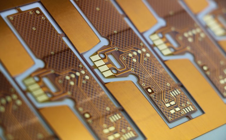
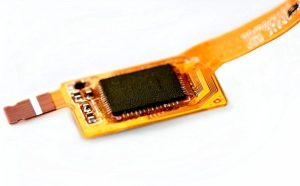
Polyimide films are commonly amber or translucent in appearance. One of the best-known polyimide films is Kapton, originally developed by DuPont and introduced commercially in the 1960s. Today, polyimide films are widely used as substrates, coverlay materials, insulation layers, and other functional materials in flexible electronics.
The combination of flexibility, dimensional stability, and high-temperature performance makes polyimide particularly suitable for flexible circuits, rigid-flex boards, high-density interconnects, and other demanding electronic applications.
Types of Polyimide Flexible PCB
Based on circuit structure, layer count, and application requirements, Polyimide Flexible PCB products can generally be divided into several categories.
Single-Sided Polyimide Flexible PCB
A single-sided flexible PCB contains one conductive copper layer on a polyimide substrate. Components and electrical connections are primarily located on one side of the circuit.
This structure is relatively simple and cost-effective, making it suitable for applications with straightforward circuit layouts and limited interconnection requirements. A coverlay may be added to protect the exposed copper traces and improve mechanical and environmental reliability.
Typical applications include sensors, keyboards, display connections, consumer electronics, and simple interconnection circuits.
Double-Sided Polyimide Flexible PCB
A double-sided flexible PCB contains copper layers on both sides of the polyimide dielectric substrate. The two conductive layers can be interconnected through plated through-holes or other suitable interconnection structures.
This configuration provides greater routing flexibility than a single-sided design and allows components or conductive features to be placed on both sides. It is often selected when circuit density is higher but a full multilayer structure is unnecessary.
Multilayer Polyimide PCB
A multilayer Polyimide PCB consists of multiple conductive layers separated by dielectric materials and interconnected through vias or plated through-holes.
Multilayer flexible circuits can provide higher circuit density, more routing channels, dedicated power and ground structures, and better electrical functionality within a compact area.
However, multilayer flexible PCB manufacturing requires careful control of layer alignment, lamination, copper thickness, via reliability, bending areas, and mechanical stress. Designers should also avoid unnecessarily placing rigid components or vias in areas intended for repeated dynamic bending.
Rigid-Flex PCB
A rigid-flex PCB combines rigid PCB sections with flexible polyimide circuit sections in a single integrated structure. The flexible portion provides mechanical movement and three-dimensional routing, while rigid sections provide stable areas for component mounting.
This structure can reduce connectors, wiring harnesses, and assembly steps while improving packaging efficiency. Rigid-flex technology is widely used in compact electronic devices, industrial equipment, medical systems, automotive electronics, and aerospace equipment.
Advantages of Polyimide PCB
The material characteristics of polyimide provide several important advantages for flexible and high-reliability electronic applications.
Excellent Flexibility
One of the most important advantages of Polyimide Flexible PCB technology is its mechanical flexibility. Polyimide films can be manufactured in thin structures, allowing the circuit to bend, fold, or conform to complex mechanical shapes.
Flexible circuits can therefore replace conventional wire harnesses or rigid interconnects in applications where space is limited. However, the allowable bend radius depends on factors such as copper type, copper thickness, layer count, coverlay construction, and whether the circuit is designed for static or dynamic bending.
For repeated bending applications, special attention should be given to bend radius, copper grain structure, trace geometry, and the placement of vias and components.
High Thermal Stability
Polyimide has excellent thermal stability compared with many conventional polymer materials. It can maintain its structural and electrical properties across a relatively wide temperature range, depending on the specific material system.
This characteristic makes polyimide attractive for electronics exposed to thermal cycling, elevated temperatures, or localized heat. It is commonly used in automotive, aerospace, industrial, and other demanding environments.
It is important to distinguish the thermal resistance of the polyimide film itself from the operating temperature of the finished PCB. The actual temperature capability of a Polyimide PCB is also influenced by copper, adhesive systems, coverlay, soldering processes, components, and other materials used in the construction.
Good Electrical Insulation
Polyimide provides reliable electrical insulation and can support stable electrical performance in flexible circuit structures.
Its dielectric characteristics can be useful in high-speed and high-density applications, but actual signal performance depends on the complete stackup, including dielectric thickness, dielectric constant, copper geometry, trace spacing, reference planes, and operating conditions.
For high-speed designs, engineers should evaluate the complete transmission-line structure rather than selecting polyimide solely based on its material properties.
Chemical Resistance
Polyimide generally demonstrates good resistance to many chemicals, solvents, oils, and other environmental factors. This property can contribute to the reliability of flexible circuits used in demanding environments.
The exact chemical resistance depends on the specific polyimide formulation and the other materials used in the PCB construction. Therefore, compatibility should be verified when the circuit will be exposed to aggressive chemicals for extended periods.
Low Weight and Thin Profile
Polyimide flexible circuits can be manufactured with very thin dielectric and copper structures. Compared with conventional rigid circuit boards and wiring assemblies, they can significantly reduce weight and installation space.
This advantage is particularly valuable in portable electronics, aerospace systems, wearable devices, cameras, and other applications where size and weight are important design considerations.
Dimensional Stability
Polyimide can provide good dimensional stability during thermal processing when an appropriate material system and manufacturing process are selected.
Stable dimensions are important for fine-pitch components, high-density routing, multilayer alignment, and precision mechanical assembly. Proper control of lamination, drilling, etching, and thermal processing is essential to achieve consistent results.
Applications of Polyimide PCB
The combination of flexibility, thermal stability, low weight, and electrical performance makes Polyimide PCB Applications increasingly diverse.
Medical Electronics
Medical devices often require compact and lightweight electronic circuits that can conform to irregular mechanical structures. Polyimide flexible circuits are suitable for many medical electronics because they can provide electrical interconnection while occupying very little space.
Applications can include medical sensors, diagnostic equipment, imaging systems, wearable monitoring devices, and disposable or semi-disposable electronic assemblies.
Flexible construction also makes it easier to integrate circuits into portable devices where traditional rigid PCBs or large cable assemblies would be difficult to install.
Consumer and Commercial Electronics
Consumer electronics are one of the most common areas for Polyimide Flexible PCB technology. Smartphones, tablets, cameras, laptops, displays, wearable devices, and other compact products frequently use flexible circuits for internal interconnections.
The thin profile of polyimide circuits allows engineers to route electrical connections around hinges, corners, batteries, displays, and other mechanical structures.
In some applications, a flexible PCB can replace multiple wires and connectors, reducing assembly complexity and saving internal space.
Automotive Electronics
Modern vehicles contain an increasing number of electronic control units, sensors, cameras, displays, lighting systems, and communication modules.
Polyimide Circuit Board technology can be used in automotive applications where circuits need to fit into small or irregular spaces and withstand vibration and thermal cycling.
Potential applications include instrument clusters, camera modules, sensor assemblies, lighting systems, infotainment equipment, control systems, and other vehicle electronics.
For automotive applications, material selection and manufacturing quality are particularly important because the circuit may experience vibration, temperature changes, humidity, and mechanical stress throughout its service life.
Aerospace and Defense Electronics
Aerospace electronics require lightweight, compact, and highly reliable interconnection solutions. Polyimide is well suited to many aerospace applications because flexible circuits can reduce the weight and volume associated with conventional wiring.
Flexible circuits can also be routed through non-planar spaces and integrated into compact electronic assemblies. Depending on the application, polyimide-based flexible circuits may be used in avionics, sensors, instrumentation, communication systems, aerospace control electronics, and other specialized equipment.
For high-reliability aerospace applications, engineers must consider the complete material system, environmental requirements, mechanical fatigue, thermal cycling, and applicable industry standards.
Industrial Electronics
Industrial equipment often requires compact sensor connections, control circuits, display interfaces, and moving electrical connections.
Polyimide flexible circuits can be useful where space is restricted or where a circuit must follow a moving mechanical structure. Their flexibility can help simplify equipment design and reduce the number of discrete cables and connectors.
How Is a Polyimide PCB Manufactured?
Polyimide PCB Manufacturing requires specialized process control because flexible substrates behave differently from conventional rigid PCB materials.
Although the exact process varies according to the PCB structure and material system, a typical manufacturing flow includes the following steps.
Material Preparation and Lamination
The manufacturing process begins with polyimide film, copper foil, adhesive materials, coverlay, or other required materials.
Copper foil is bonded to the polyimide substrate through an appropriate bonding or lamination process. Depending on the construction, adhesive-based or adhesiveless copper-clad polyimide materials may be used.
Lamination parameters such as temperature, pressure, time, and material thickness must be carefully controlled to achieve reliable bonding and dimensional stability.
Circuit Imaging and Etching
After the copper-clad material is prepared, the required circuit pattern is transferred to the copper surface.
A photoresist is applied and exposed through an imaging process. The exposed material is developed to form the required etching pattern. Unwanted copper is then removed through a controlled chemical etching process.
The remaining copper forms the conductive traces, pads, and other circuit features.
For fine-line Polyimide PCB designs, accurate imaging and etching control are essential to maintain trace width, spacing, and dimensional accuracy.
Drilling and Via Formation
Depending on the circuit structure, holes and vias are created using mechanical drilling, laser drilling, or other suitable technologies.
Vias provide electrical connections between different conductive layers. After drilling, the hole walls may undergo desmear and conditioning processes before copper plating.
For multilayer flexible circuits, via reliability is particularly important because mechanical bending and thermal cycling can place additional stress on interconnections.
Copper Plating
For boards requiring plated through-holes or other plated structures, copper is deposited onto the hole walls and circuit surfaces through an electrochemical plating process.
The plating thickness and uniformity must be carefully controlled to provide reliable electrical connections and sufficient mechanical durability.
Coverlay and Solder Mask
Flexible PCBs commonly use polyimide coverlay to protect copper traces and provide electrical insulation. Depending on the design, flexible solder mask or other protective coatings may also be used.
The protective layer helps reduce the risk of oxidation, contamination, electrical shorts, and mechanical damage.
In bend areas, the coverlay construction must be designed carefully so that it does not unnecessarily increase stiffness or reduce flexibility.
Surface Finish
Depending on component requirements and the intended application, the exposed copper pads may receive a suitable surface finish such as ENIG or another qualified finish.
Surface finish selection affects solderability, contact reliability, storage performance, and manufacturing cost. The appropriate finish should therefore be selected according to the assembly process and end-use environment.
Silkscreen and Marking
The final manufacturing stages may include screen printing or other marking processes to identify component references, polarity indicators, assembly information, or other required markings.
Because flexible PCBs often have limited surface area, marking design should consider readability without interfering with pads, bend zones, or other functional areas.
Electrical Testing and Quality Inspection
After fabrication, the Polyimide PCB Manufacturing process typically includes visual inspection and electrical testing.
Depending on product requirements, manufacturers may perform continuity and isolation testing, dimensional inspection, solderability evaluation, surface inspection, and other reliability or process-specific tests.
For high-reliability applications, additional testing may be required to verify the circuit’s performance under thermal, mechanical, humidity, or other environmental conditions.
Key Design Considerations for Polyimide Flexible PCB
Designing a reliable Polyimide Flexible PCB requires more than simply replacing an FR-4 substrate with polyimide.
Engineers should consider the following factors:
- Bend radius: Dynamic bending generally requires a larger design margin and more careful material selection than static bending.
- Copper selection: Rolled annealed (RA) copper is commonly preferred for applications involving repeated flexing because of its favorable fatigue characteristics.
- Trace routing: Avoid sharp corners and unnecessary stress concentrations in bend regions.
- Via placement: Keep vias and rigid structures away from areas that undergo repeated bending whenever possible.
- Layer count: More layers generally increase stiffness, so the stackup should be optimized according to the required electrical and mechanical performance.
- Coverlay design: Coverlay openings, thickness, and material selection affect both protection and flexibility.
- Component placement: Heavy or rigid components should normally be kept away from dynamic bending zones.
- Thermal requirements: The complete material stack, rather than polyimide alone, determines the actual thermal performance of the finished circuit.
- Impedance requirements: High-speed flexible circuits may require controlled impedance based on trace geometry, dielectric thickness, copper thickness, and the selected polyimide system.
Polyimide PCB vs. FR-4 PCB
Polyimide and FR-4 serve different design purposes. FR-4 is widely used for rigid circuit boards because of its mechanical rigidity, cost efficiency, and broad manufacturing availability. Polyimide is particularly valuable when flexibility, thinness, thermal stability, or resistance to demanding environments is required.
| Feature | Polyimide PCB | FR-4 PCB |
|---|---|---|
| Flexibility | Excellent for flexible circuit designs | Primarily rigid |
| Weight | Very low in flexible constructions | Generally higher |
| Thermal stability | Excellent | Good, depending on grade |
| Mechanical structure | Flexible | Rigid |
| Typical use | Flexible and rigid-flex circuits | Rigid PCBs |
| Space efficiency | Excellent | Good |
| Manufacturing cost | Generally higher | Generally lower |
The right choice depends on the mechanical structure, electrical requirements, thermal environment, reliability expectations, and overall cost target of the product.
Why Choose Kingda for Polyimide PCB Solutions?
Kingda provides PCB manufacturing and engineering support for customers requiring customized circuit board solutions, including flexible and high-reliability PCB applications.
For Polyimide PCB Applications, successful manufacturing depends on more than substrate selection. Material compatibility, circuit geometry, layer structure, copper thickness, coverlay design, bending requirements, surface finish, and electrical testing must all be considered together.
Kingda can work with customers to evaluate PCB specifications and develop manufacturing solutions based on the application’s electrical, mechanical, and environmental requirements.
Engineering Support
A reliable flexible PCB begins with a manufacturable design. Kingda can support design evaluation and manufacturing preparation to help identify potential issues related to trace spacing, bend areas, vias, component placement, stackup, and material selection.
Quality-Focused Manufacturing
Consistent process control is important for flexible circuits because thin materials can be more sensitive to dimensional variation and mechanical handling. Kingda focuses on controlling key manufacturing parameters throughout fabrication and inspection.
Customized Solutions
Different applications require different polyimide materials, copper thicknesses, layer structures, coverlay configurations, and surface finishes. Kingda can provide customized PCB solutions according to the customer’s drawings, specifications, and application requirements.
Reliable Delivery
Efficient production planning, process coordination, and quality inspection help support stable delivery for prototype and production requirements. Kingda works with customers to coordinate manufacturing requirements and provide practical PCB solutions.
Conclusion
Polyimide PCB technology is an important solution for modern flexible electronics. Its combination of flexibility, low weight, thermal stability, electrical insulation, chemical resistance, and thin construction makes it suitable for applications ranging from consumer electronics and medical devices to automotive, industrial, and aerospace systems.
However, achieving reliable performance requires more than choosing polyimide as the substrate. Bend radius, copper type, layer structure, coverlay, via design, component placement, thermal conditions, and manufacturing processes must all be considered during PCB development.
With appropriate material selection, professional Polyimide PCB Manufacturing, and careful design-for-manufacturing practices, polyimide flexible circuits can provide compact, reliable, and durable interconnection solutions for increasingly demanding electronic products.