Foldable Phone FPC: Why Hinge Interconnect Is Getting Harder
Foldable phones stopped being a niche category the moment three major brands began competing for the same buyers. Panel shipments are expected to grow by roughly a quarter in 2026, and the mix is shifting toward larger book style devices that behave like small tablets when opened. Every one of those devices depends on a foldable phone FPC that crosses the hinge several times a day.
That shift matters more to board suppliers than the volume number does. A larger inner display, a thinner body and more sensors inside the same hinge mean the foldable phone FPC is no longer a simple connecting cable. It has become a structural element that decides how the whole product folds.
What the Shipment Numbers Hide
Growth of twenty percent sounds like a volume story, and for some component categories it is. For flexible circuits the meaningful change is complexity per unit. A book style device uses more separate flexible runs than an early clamshell design, and several of them sit in areas that move every time the phone is opened or closed.
Manufacturers therefore face two problems at once: more flexible interconnect to build, and a tighter reliability requirement on each of those parts. A process that was adequate for a simple display cable is usually not adequate for a hinge assembly that also carries camera traffic and power.
Why Book Style Devices Change the Layout
When the inner screen grows, the electronics no longer fit on one rigid board. Camera modules, the display driver, radio components and the battery are distributed across both halves of the device, and everything that crosses between them has to pass through the hinge region, which is the thinnest and most mechanically active part of the phone.
The hinge is also where space is contested most aggressively. Every tenth of a millimetre taken by a cable is a tenth of a millimetre unavailable to the battery or the enclosure. This is why designers push flexible circuits thinner while asking them to carry more signals than the generation before.
Where Flexible Circuits Are Used Inside
A modern foldable contains several distinct flexible assemblies. One links the main board to the display, another serves the camera cluster, and further runs handle the sub display, the antenna feed and the hinge sensing electronics. Each has its own bend geometry and its own reliability expectation.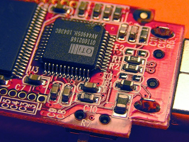
Some of these are pure connectors. Others integrate components directly, with chips, filters or connectors mounted on the flex itself. That integration reduces the number of connectors in the product, but it also means the flexible circuit must survive the reflow process as well as the folding motion.
Bend Life Becomes a Design Specification
Consumers open and close a foldable device tens of thousands of times over its life, and every cycle loads the conductors passing through the hinge. The relevant specification is not a generic flexibility claim but a measured bend life under a defined radius and a defined number of cycles.
Designers influence that number through geometry. Conductors running perpendicular to the bend axis share the load evenly, while conductors that turn inside the moving region concentrate stress at the corners. Small layout decisions made early determine whether the part passes qualification later.
Materials That Survive Repeated Folding
Copper type matters more in a folding product than in almost any other application. Rolled annealed foil has a grain structure that tolerates repeated strain far better than electrodeposited foil, which is why it dominates dynamic flex designs despite costing more.
The laminate beneath it matters as well. Adhesiveless constructions remove an acrylic layer that can creep under load and delaminate over time, so they are preferred wherever the circuit actually moves. The result is a thinner stack with better dimensional stability and more predictable fatigue behaviour.
Coverlay, Stiffener and Bend Radius
Coverlay protects the conductors and defines the neutral axis of the bend. Thickness variation in the coverlay changes where the strain falls, which is why a film applied unevenly in the moving zone can shorten the fatigue life of an otherwise correct design.
Stiffeners serve the opposite purpose by making selected areas rigid enough for connectors and component attachment. Their placement is a compromise. A stiffener that ends too close to a bend creates a hard transition where cracks begin, so the distance between reinforcement and motion is a deliberate dimension rather than an aesthetic choice.
Fine Lines and Microvias in Flex
The number of signals crossing the hinge keeps rising, and the width of the hinge does not. Dense routing in a thin dielectric therefore depends on fine line capability and on microvias that allow a change of layer without a mechanically drilled hole through the whole stack.
Microvias in flexible material behave differently from microvias in rigid laminate, because the base film is thinner and more compliant. Plating quality, via capture pad design and dielectric thickness all have to be controlled together, which puts real HDI and flex capability at the centre of foldable supply.
Rigid Flex Replaces Connectors
Where a component needs mechanical support, a rigid section is still required. A rigid flex construction places that section and the flexible cross hinge connection on the same board, eliminating a pair of connectors and the assembly step that mates them.
Each connector removed improves both reliability and thickness. The trade is process difficulty, because bonding rigid and flexible layers reliably, while keeping registration and surface flatness inside tolerance, requires equipment and experience that general purpose fabricators may not have. Partners who build flexible circuit assemblies routinely treat this as their core competence.
Impedance Through a Moving Section
High speed interfaces continue to move into foldable designs, which means differential pairs must keep their impedance not only across the board but through the bending region. A change of material, thickness or line geometry along that path changes impedance and degrades the link.
Keeping impedance stable through a moving section is difficult because the ideal electrical construction is not always the ideal mechanical one. Designers and fabricators have to negotiate: a slightly wider trace may be acceptable electrically if it improves fatigue life, and a slightly thinner coverlay may be acceptable mechanically if the impedance window permits it.
Display Driver and Camera Links
Two interfaces dominate the signal budget in a folding phone. The display link carries very high data rates over a short distance, while the camera link carries a similar volume from a module that has to keep working while the device moves.
Both are sensitive to loss and reflection, and both cross the hinge. That combination is why foldable designs push flex technology harder than tablets or laptops do, even though those products also use flexible circuits extensively.
The Assembly Challenge on Thin Boards
Populating a flexible circuit is harder than populating a rigid board of the same area. Thin substrates warp during reflow, fine pitch parts need accurate placement, and the panel has to be supported without marking the film. Solder paste volume differences that would be harmless on a rigid board can crack a component on a flex.
This is where fabrication and board level testing need to be coordinated rather than sequential. When a placement defect appears, the trace data from the flex manufacturing side is the fastest route to the cause.
Testing Moving Interconnect
A flexible assembly that passes electrical test in a flat position has not been validated. Dynamic bend testing, repeated folding fixtures and inspection of the bend zone after cycling are all needed to demonstrate that a design will survive a product lifetime.
Impedance changes during bending are also worth measuring, because a link that works when stationary may not work when the device is in motion. Very few failures are dramatic; most appear as intermittent behaviour that is difficult to reproduce later.
Why This Capability Travels to Other Products
Once a factory can build reliable dynamic flex and rigid flex, the same capability serves wearables, robotics and medical instruments. Those markets differ in certification but share the fundamental requirement of interconnect that survives movement.
This overlap is why foldable phones act as a technology driver beyond their own volume. The process learning paid for by one consumer category is directly applicable to products that will grow later, which improves the return on that investment.
Cost Drivers Beyond Material
Material cost is visible on a quotation, but yield is where the real difference between suppliers appears. Dynamic flex has many opportunities for loss, and the price of a part that fails qualification is far higher than the price of a part that works.
Tooling, panel utilisation and the number of process steps also matter, particularly when a design uses rigid flex and therefore consumes both rigid and flexible process capacity. Reviewing these layout and construction choices early is the most effective way to control them.
What to Ask a Flex Supplier
Ask which copper foil is used for the bending layers, how the neutral axis is managed and what bend radius the design assumes. Ask how microvias in flexible material are inspected, since destructive cross sectioning cannot be the only method.
Then ask about process ownership. A supplier that controls lamination, drilling, plating and assembly under one manufacturing process can answer those questions with data from its own floor. A supplier that outsources a critical step has to guess, and guessing is expensive in a product that folds every day.