Press-Fit PCB Connectors: PCB Design, PCB Manufacturing & Press-Fit Technology
As modern electronic systems integrate more components, modules, and subassemblies into increasingly compact platforms, reliable electrical interconnection has become a critical part of PCB Design. Engineers must develop connection technologies that provide mechanical stability, electrical performance, manufacturability, and long-term reliability without unnecessarily increasing product size.
Press-fit PCB connectors provide an alternative to conventional soldered interconnections. Instead of relying on solder to attach a connector terminal to the PCB, press-fit technology uses specially designed compliant pins that are mechanically inserted into plated through-holes.
Originally adopted extensively in automotive electronics, press-fit interconnection technology has expanded into industrial, telecommunications, power electronics, aerospace, and other applications where robust and serviceable electrical connections are required.
This article explains how press-fit PCB technology works, its major advantages and limitations, design considerations, manufacturing requirements, and common applications.
What Is Press-Fit PCB Technology?
Press-fit PCB technology is an interconnection method in which a specially designed terminal or pin is mechanically inserted into a plated through-hole (PTH) in a printed circuit board.
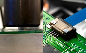
Unlike a conventional soldered connector, a press-fit terminal does not require solder to establish the primary electrical connection.
A typical press-fit pin contains a compliant section designed to deform elastically during insertion. The compliant section is generally slightly wider than the effective opening of the plated hole.
During insertion:
- The press-fit pin enters the plated through-hole.
- The compliant section deforms within its designed elastic range.
- The pin generates controlled contact force against the plated copper barrel.
- The resulting gas-tight or highly stable contact interface provides electrical conductivity.
- Mechanical friction and elastic restoring force help retain the connector.
The actual pin geometry, hole diameter, plating thickness, insertion force, retention force, and allowable deformation are determined by the connector manufacturer’s specifications.
Therefore, successful PCB Manufacturing requires close control of both the PCB hole and the press-fit terminal dimensions.
How Does a Press-Fit Connection Work?
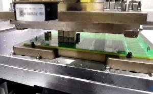
A press-fit connection depends on controlled mechanical interference rather than solder.
The most important element is the compliant section of the terminal. Common designs allow the terminal to deform during insertion while limiting the mechanical stress transferred to the PCB.
The connection must provide enough contact force to maintain electrical continuity, but excessive force can damage the plated through-hole or surrounding laminate.
A properly designed press-fit connection therefore requires a balance between:
- Pin geometry
- Hole diameter
- Hole tolerance
- Copper plating
- PCB laminate
- Insertion force
- Retention force
- Connector housing
- Operating temperature
- Vibration and mechanical loads
The goal is to maintain a stable electrical connection without exceeding the mechanical limits of the PCB.
Press-Fit vs. Soldered PCB Connections
Press-fit and soldered connections are both widely used, but they address different design and manufacturing requirements.
| Feature | Press-Fit Connection | Soldered Connection |
|---|---|---|
| Primary connection mechanism | Mechanical contact | Solder joint |
| Solder required | No | Yes |
| Thermal exposure during connector installation | Low | Higher |
| Reworkability | Generally easier for compatible connectors | Can require desoldering |
| Manufacturing process | Requires controlled insertion | Requires soldering process |
| Hole requirements | Tight dimensional control | Also requires controlled hole geometry |
| Mechanical reliability | Depends on connector and PCB design | Depends on solder-joint design and process |
| Vibration performance | Can be excellent when properly designed | Can also be excellent when properly designed |
| Serviceability | Often advantageous | Depends on connector design |
| Initial connector cost | May be higher | Often lower |
| Best use case | High-volume, serviceable, robust interconnections | Broad range of PCB assemblies |
It is important not to assume that press-fit connections are universally more reliable than soldered connections. Both technologies can achieve high reliability when appropriately designed, manufactured, assembled, and qualified for the intended environment.
Applications of Press-Fit PCB Technology
Press-fit interconnection has expanded significantly beyond its early automotive applications.
Automotive Electronics
Automotive electronics are among the most prominent applications for press-fit technology.
Modern vehicles contain numerous electronic control units and electrical modules that must withstand:
- Vibration
- Mechanical shock
- Temperature cycling
- Humidity
- Automotive fluids
- Long operating periods
Press-fit connectors can be used in applications such as:
- Engine control modules
- Transmission control modules
- Battery management systems
- Automotive power electronics
- ADAS systems
- Body-control modules
- Sensor interfaces
- Electric vehicle systems
The suitability of a press-fit connection depends on the specific connector design and environmental qualification requirements.
Industrial Automation
Industrial control equipment often operates in environments exposed to vibration, dust, humidity, and temperature variation.
Press-fit connectors can provide a mechanically robust interface between PCBs and external modules while reducing the need for soldered connector installation.
Applications include:
- PLC systems
- Motor controllers
- Industrial sensors
- Automation equipment
- Robotics
- Factory control systems
- Power-control equipment
Telecommunications and Networking
High-density telecommunications equipment requires compact interconnections and controlled electrical performance.
Press-fit connector systems can be integrated into backplanes, daughtercards, and high-density PCB assemblies.
For high-speed applications, connector geometry, differential-pair routing, impedance discontinuities, insertion loss, return loss, and crosstalk must be evaluated as part of the complete interconnect system.
Power Electronics
Press-fit technology can also be used in certain power-electronics applications.
However, current-carrying capability depends on the connector terminal, contact resistance, conductor geometry, thermal environment, and number of parallel contacts. A press-fit connector should therefore not automatically be considered a high-power solution simply because it eliminates solder.
For high-current applications, engineers should verify the manufacturer’s current rating and thermal derating data.
Aerospace and Defense Electronics
High-reliability applications can use press-fit connectors when they require serviceable and mechanically robust interconnections.
Potential applications include:
- Avionics
- Communication systems
- Control electronics
- Power distribution
- Radar systems
- Mission electronics
Qualification requirements in these applications can be considerably more demanding than those for commercial products.
Best Practices for Press-Fit PCB Design and Manufacturing
To obtain reliable press-fit connections, engineers should consider the interconnection during the earliest stages of PCB Design.
1. Follow the Connector Manufacturer’s Specifications
The connector manufacturer’s datasheet should be treated as the primary reference for:
- Finished hole diameter
- Hole tolerance
- Terminal geometry
- Insertion force
- Extraction force
- Recommended PCB thickness
- Copper plating requirements
- Permitted PCB materials
- Connector spacing
- Assembly tooling
Generic press-fit dimensions should not replace the specific manufacturer’s requirements.
2. Control Finished Hole Diameter
Hole diameter is one of the most important parameters in press-fit PCB production.
If the hole is too small, excessive insertion force can:
- Damage the plated barrel
- Crack the laminate
- Delaminate the PCB
- Distort the connector terminal
- Reduce manufacturing yield
If the hole is too large, contact force may be insufficient, potentially reducing electrical and mechanical reliability.
The finished hole diameter must therefore account for drilling, plating, and manufacturing tolerances.
3. Control Plated Through-Hole Quality
Because the terminal directly contacts the plated hole, the quality of the PTH barrel is critical.
Manufacturers should control:
- Copper plating thickness
- Barrel uniformity
- Hole diameter
- Hole position
- Plating adhesion
- Surface condition
- Lamination quality
The exact copper-plating requirement depends on the PCB specification and connector manufacturer’s requirements rather than one universal thickness.
4. Consider PCB Thickness and Mechanical Strength
Press-fit insertion generates mechanical force that must be transferred through the PCB.
Thin or mechanically weak boards may require additional structural support.
Engineers should evaluate:
- PCB thickness
- Laminate strength
- Layer count
- Hole density
- Connector dimensions
- Distance between holes
- Distance from holes to board edges
- Local copper distribution
Additional reinforcement may be required for high-density connector fields.
5. Design Adequate Pad and Annular Ring Geometry
The copper land surrounding the press-fit hole must provide sufficient mechanical support.
Insufficient annular ring can increase the risk of pad lifting or barrel damage during insertion.
Pad geometry should therefore be developed based on the connector manufacturer’s recommended PCB footprint and the PCB fabricator’s capabilities.
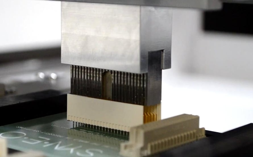
6. Use Controlled Insertion Equipment
Press-fit connectors should generally be installed using controlled tooling rather than manually forcing the connector into the PCB.
Controlled equipment can provide:
- Consistent insertion force
- Controlled insertion speed
- Proper alignment
- Reduced PCB stress
- Repeatable assembly quality
For high-volume production, automated or semi-automated press-fit equipment can improve consistency and manufacturing efficiency.
Key Mechanical and Electrical Parameters
Several parameters should be evaluated before selecting a press-fit connector.
Insertion Force
Insertion force is the force required to insert the terminal into the PCB hole.
It depends on:
- Terminal geometry
- Hole diameter
- Contact design
- Number of pins
- PCB material
- Plating
- Insertion speed
The total insertion force for a connector can become substantial when hundreds of pins are inserted simultaneously.
Retention Force
Retention force determines how strongly the terminal remains mechanically engaged with the PCB.
A reliable press-fit connection must maintain sufficient retention throughout the intended vibration and mechanical environment.
Contact Resistance
Contact resistance should remain stable throughout the expected operating life.
Factors affecting contact resistance include:
- Contact pressure
- Surface condition
- Oxidation
- Contamination
- Temperature
- Mechanical movement
Low and stable contact resistance is particularly important for power and high-speed applications.
Hole Tolerance
Press-fit technology is highly sensitive to finished hole dimensions.
The acceptable tolerance should be specified according to the connector manufacturer’s requirements and the PCB fabricator’s process capability.
Copper Plating
The plated barrel must withstand the mechanical stress created during insertion and maintain electrical continuity throughout the product life.
Plating quality should therefore be verified during PCB Manufacturing.
Advantages of Press-Fit PCB Technology
Press-fit technology offers several important benefits when the application is properly designed.
No Solder Required
The primary advantage is that the connector can be installed without a conventional soldering operation.
This can eliminate or reduce:
- Solder-related defects
- Flux residues
- Reflow exposure
- Wave-solder processing
- Thermal stress associated with connector soldering
Reduced Thermal Stress
Because the connector does not need to undergo a soldering thermal cycle during installation, the PCB and connector can experience less localized thermal exposure.
This can be useful for heat-sensitive components or assemblies where minimizing additional thermal processing is desirable.
Good Mechanical Stability
The compliant pin maintains mechanical contact with the plated hole.
When correctly designed, press-fit connections can provide strong resistance to vibration and mechanical shock.
Easy Maintenance and Replacement
Some press-fit connector systems can be removed and replaced without conventional desoldering.
This can simplify:
- Maintenance
- Module replacement
- Field servicing
- Connector replacement
- Certain rework operations
However, the number of permissible insertion and extraction cycles depends on the connector design.
Compatibility With Lead-Free Manufacturing
Because press-fit technology does not require solder for the connector interface, it can reduce the solder-processing requirements associated with connector installation.
It can therefore complement lead-free manufacturing strategies.
Suitable for High-Density Interconnections
Press-fit connectors can integrate a large number of electrical contacts into compact connector housings.
This makes them useful for:
- Backplanes
- Daughtercards
- Automotive modules
- Industrial control systems
- Telecommunications equipment
Limitations of Press-Fit PCB Technology
Despite its advantages, press-fit technology is not suitable for every PCB.
High Mechanical Stress
The insertion process generates mechanical forces that must be supported by the PCB.
Very thin PCBs, flexible circuits, or mechanically weak constructions may require additional reinforcement or a different connection technology.
Tight Manufacturing Tolerances
Press-fit connections require accurate control of:
- Hole diameter
- Hole position
- Plating thickness
- PCB thickness
- Connector pin geometry
Manufacturing variation outside the specified range can result in excessive insertion force or inadequate contact pressure.
Higher Initial Component Cost
Press-fit connector systems can have higher component or tooling costs than simple soldered connectors.
However, total cost should be evaluated across the complete production process, including soldering, thermal processing, inspection, rework, maintenance, and service requirements.
Specialized Assembly Equipment
High-density press-fit connectors generally require appropriate insertion tooling.
Manual installation can create inconsistent force and alignment and may increase the risk of PCB damage.
Limited Compatibility With Some PCB Structures
Very thin, flexible, or highly delicate boards may not provide enough mechanical strength for press-fit insertion.
Engineers must evaluate the PCB structure before selecting this technology.
Testing and Quality Control
After press-fit assembly, both mechanical and electrical characteristics should be verified according to the product requirements.
Possible tests include:
Contact Resistance Testing
Measures the electrical resistance of the press-fit interface.
Stable low contact resistance is important for long-term electrical performance.
Pull-Out or Retention Testing
Determines the mechanical force required to remove the connector or terminal.
Insertion Force Testing
Confirms that the assembly process remains within the specified force range.
Vibration Testing
Evaluates connection stability under mechanical vibration.
This is particularly important for automotive, industrial, aerospace, and other mechanically demanding applications.
Thermal Cycling
Thermal cycling can be used to evaluate the connection under repeated temperature changes.
The test profile should be determined according to the product’s operating environment and applicable qualification standard.
Cross-Section Analysis
For process qualification or failure analysis, PCB cross-sections can be used to examine:
- Plated-hole integrity
- Copper thickness
- Terminal deformation
- Hole geometry
- Cracks
- Delamination
The specific test methods and acceptance criteria should be defined by the product specification, connector manufacturer, and applicable industry standards.
Press-Fit PCB Design Considerations
When implementing press-fit technology, engineers should evaluate the complete interconnection rather than treating the connector as an isolated component.
Important considerations include:
- Mechanical design — Ensure the PCB can withstand insertion and extraction forces.
- Electrical design — Verify current capacity, voltage rating, contact resistance, and signal-integrity requirements.
- Thermal design — Evaluate temperature rise and thermal expansion.
- PCB fabrication — Control finished hole dimensions and plating quality.
- Assembly tooling — Select equipment capable of providing controlled insertion force.
- Service requirements — Determine whether the connector must support repeated removal and replacement.
- Environmental conditions — Consider vibration, shock, humidity, temperature, and chemical exposure.
- Manufacturing yield — Design appropriate tolerances to minimize assembly defects.
These considerations should be incorporated into the design before PCB production begins.
Conclusion
Press-fit PCB technology provides a practical alternative to soldered connector interconnections for applications requiring robust mechanical retention, reliable electrical contact, serviceability, and reduced solder-processing requirements.
By using compliant pins inserted into precisely controlled plated through-holes, press-fit connectors can provide stable electrical and mechanical connections without relying on solder.
However, successful implementation depends heavily on accurate PCB Design and controlled PCB Manufacturing. Hole diameter, plating quality, annular-ring geometry, PCB thickness, connector specifications, insertion force, and assembly tooling must all be carefully coordinated.
Press-fit technology is particularly relevant to automotive, industrial, telecommunications, power electronics, aerospace, and other applications where reliable modular interconnections are important. As electronic systems continue to become smaller and more integrated, advances in compliant-pin geometry, high-density connectors, and precision PCB fabrication are likely to expand the range of applications for press-fit interconnection technology.
For projects requiring precision PCB fabrication, high-density interconnects, press-fit connector integration, and reliable PCB Assembly, Kingda can support engineers from PCB Design through manufacturing and assembly.