How to Test a Capacitor on a PCB: PCB Design & PCB Manufacturing Guide
In modern electronic applications, using a printed circuit board (PCB) to implement electrical and logical functions has become standard practice. A PCB provides the physical platform on which electronic components are interconnected to form functional circuits. When an input is applied, the connected components work together according to the circuit topology to produce the required output.
Capacitors are among the most widely used components on a PCB. They store and release electrical energy, filter unwanted signals, stabilize power rails, and reduce voltage fluctuations. Because capacitors are frequently exposed to electrical, thermal, and ripple-current stress, they can become a common source of circuit problems.
A capacitor is a two-terminal passive electronic component consisting of two conductive electrodes separated by a dielectric material. One of its fundamental characteristics is its ability to block steady-state DC while allowing AC components to pass, although its actual behavior depends on frequency and the capacitor’s impedance characteristics.
When troubleshooting a PCB, identifying a defective capacitor can be challenging, especially when the goal is to test the component without removing it from the board. Fortunately, several techniques can be used for PCB capacitor testing, including visual inspection, multimeter testing, ESR measurement, oscilloscope analysis, and, when necessary, LCR measurement.
This guide explains how to test a capacitor on a PCB and how to improve measurement accuracy while minimizing unnecessary board rework.
Signs of a Failed Capacitor on a PCB
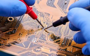
PCB troubleshooting should begin with a careful examination of abnormal circuit behavior. A circuit failure can originate from many different components, so symptoms should be evaluated together with electrical measurements rather than assuming that the capacitor is always the cause.
Common symptoms that may be associated with a defective capacitor include:
- The PCB fails to power on.
- The circuit shuts down or restarts unexpectedly.
- Excessive ripple appears on a power rail.
- Audible buzzing or abnormal noise occurs.
- A power supply section becomes unusually hot.
- Output signals become unstable or distorted.
- A circuit takes longer than expected to start.
- A regulated voltage fluctuates outside its normal range.
- The capacitor shows visible swelling, leakage, cracking, or discoloration.
These symptoms are not exclusive to capacitor failures. Similar behavior can result from faulty ICs, damaged traces, poor solder joints, power-supply problems, or other defective components. Therefore, capacitor testing should be combined with systematic circuit diagnosis.
PCB Capacitor Testing Methods
The appropriate testing method depends on the capacitor type, circuit design, accessibility, and diagnostic objective.
Common PCB capacitor types include electrolytic, tantalum, ceramic, and film capacitors. They are available in both through-hole (PTH) and surface-mount (SMD) packages. Their electrical characteristics, polarity, capacitance, ESR, voltage rating, and failure modes can differ significantly.
The following methods can help determine whether a capacitor is functioning correctly.
1. Prepare the PCB Before Testing
Safety and preparation should come before measurement.
Capacitors can retain electrical charge even after a PCB has been disconnected from its power source. Before testing, disconnect the PCB from all external power supplies and allow stored energy to dissipate.
For large capacitors, additional discharge procedures may be necessary. A suitable discharge resistor can be used to reduce the stored voltage in a controlled manner. Avoid simply shorting a charged capacitor with a metal tool because the resulting current surge can damage the capacitor, PCB traces, or test equipment.
Before beginning PCB testing, prepare the appropriate equipment, such as:
- Digital multimeter
- ESR meter
- LCR meter
- Oscilloscope
- Suitable probes and test leads
- Magnifying glass or microscope
- ESD protection equipment
- Appropriate discharge resistor
For sensitive electronics, use proper ESD precautions throughout the inspection and repair process.
2. Perform a Visual Inspection
Visual inspection is often the fastest way to identify a potentially defective capacitor.
For electrolytic capacitors, a bulging top, swollen casing, leakage, or damaged vent can indicate internal degradation. Discoloration, cracking, corrosion, or burn marks may also indicate excessive electrical or thermal stress.
For SMD capacitors, inspection under magnification can reveal:
- Cracked ceramic bodies
- Burn marks
- Damaged terminals
- Discoloration
- Mechanical damage
- Poor solder joints
- Signs of board contamination
However, visual inspection cannot identify every defective capacitor. Many capacitors fail electrically while retaining a normal external appearance. Therefore, electrical measurements are often required.
3. Test the Capacitor with a Multimeter
A digital multimeter is one of the most accessible tools for PCB capacitor testing.
If the multimeter has a capacitance measurement function, disconnect the PCB power and ensure the capacitor has been safely discharged. Then connect the probes to the capacitor terminals and observe the measured capacitance.
Compare the reading with the capacitor’s rated value and specified tolerance.
For example, if a capacitor is marked with a nominal capacitance and a defined tolerance range, a reading outside that range may indicate a problem. However, in-circuit measurements can be affected by other components connected in parallel or through other circuit paths.
If the multimeter does not have a capacitance mode, resistance mode can sometimes provide a basic indication of capacitor condition.
A capacitor may initially show a relatively low resistance as it begins charging from the meter’s test voltage. The displayed resistance may then increase toward a high or overload reading.
Typical observations include:
- Shorted capacitor: resistance remains very low.
- Open capacitor: little or no normal charging behavior is observed.
- Potentially functional capacitor: resistance initially changes and then rises substantially.
This resistance-mode method is only a basic diagnostic technique. It cannot reliably determine capacitance value, ESR, leakage current, or frequency-dependent performance.
For polarized capacitors, observe polarity when the test method or instrument requires it. Electrolytic and tantalum capacitors must be handled carefully because incorrect voltage polarity can damage them.
4. Test ESR with an ESR Meter
Equivalent Series Resistance (ESR) is an important parameter when evaluating capacitor condition, particularly for electrolytic capacitors used in power supplies and filtering circuits.
An ESR meter is especially useful when the goal is to test a capacitor while it remains installed on the PCB. Many ESR meters use a low-amplitude test signal, allowing certain in-circuit measurements without requiring the capacitor to be fully removed.
To perform the test:
- Turn off and isolate the PCB from its power source.
- Safely discharge the capacitor.
- Connect the ESR meter probes to the capacitor terminals.
- Read the ESR value.
- Compare the result with the expected value for the capacitor type and application.
A significantly elevated ESR can indicate aging, drying of the electrolyte, internal degradation, or excessive thermal stress.
ESR measurements are particularly valuable in switching power supplies, voltage regulators, DC-DC converters, and other circuits where capacitors experience significant ripple current.
However, in-circuit measurements can still be influenced by parallel components and PCB circuit paths. The measurement should therefore be interpreted in the context of the circuit and the capacitor’s specifications.
5. Use an Oscilloscope for Dynamic Testing
An oscilloscope can provide much more information than a simple capacitance or resistance measurement because it allows engineers to observe voltage behavior over time.
In analog, power, and high-frequency circuits, capacitor performance can directly influence ripple, transient response, noise, and signal integrity.
A practical PCB troubleshooting procedure is to measure the voltage across the capacitor while the circuit is operating under controlled conditions. The resulting waveform can reveal:
- Excessive voltage ripple
- Unexpected spikes
- Oscillation
- Slow charging or discharging
- Abnormal transient response
- Distorted or unstable signals
For example, in a power-supply circuit, an aging electrolytic capacitor with increased ESR may cause significantly higher output ripple than expected.
An oscilloscope can also be used to examine charging and discharging behavior. With an appropriate resistor-capacitor network, the voltage across the capacitor follows an RC charging or discharging curve.
The ideal time constant is:
τ = R × C
where:
- τ is the RC time constant,
- R is resistance,
- C is capacitance.
Comparing the measured waveform with the expected response can help identify abnormal capacitor behavior.
When making measurements on powered circuits, use appropriate oscilloscope grounding and probing techniques. Incorrect probing can create unintended shorts or introduce misleading high-frequency noise.
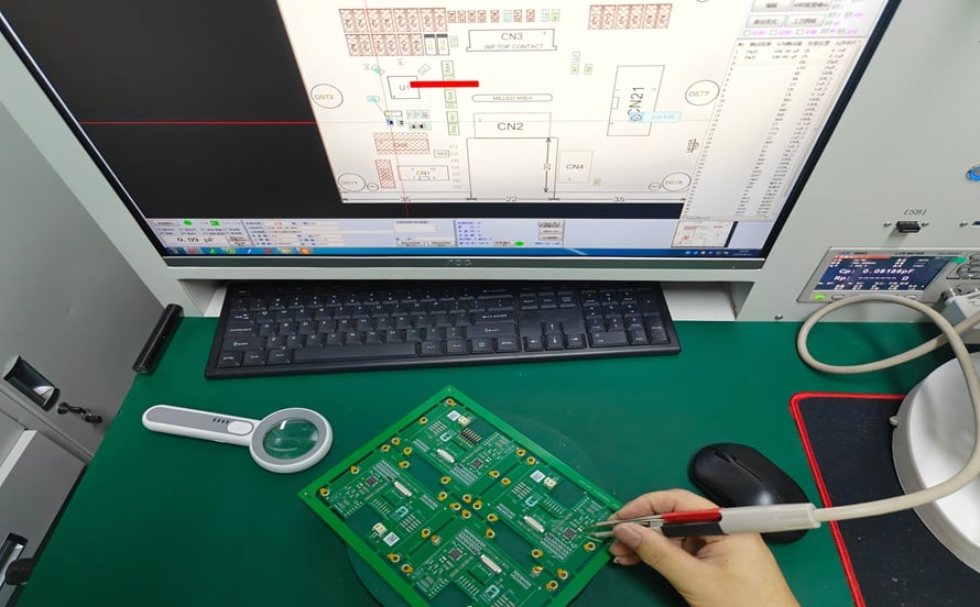
6. Use an LCR Meter for More Precise Measurement
An LCR meter measures inductance (L), capacitance (C), and resistance (R), and can provide more detailed information about a capacitor than a basic multimeter.
An LCR meter can be used to measure parameters such as:
- Capacitance
- Equivalent series resistance
- Dissipation factor
- Quality factor
- Impedance at a specified test frequency
For the most accurate evaluation, the capacitor is often removed from the PCB so that surrounding circuit components do not influence the measurement.
Select an appropriate test frequency according to the capacitor’s datasheet and application. Then compare the measured values with the manufacturer’s specifications.
This method is particularly useful when a capacitor appears visually normal but its electrical performance is questionable.
For some troubleshooting cases, engineers may first perform an in-circuit measurement and then remove the capacitor for confirmation if the initial result is ambiguous.
In-Circuit Testing vs. Removing the Capacitor
One of the most important considerations in PCB testing is whether the capacitor should remain installed during measurement.
| Testing Method | Capacitor Removed? | Typical Use | Accuracy |
|---|---|---|---|
| Visual inspection | No | Physical damage | Basic |
| Multimeter resistance test | No | Short/open screening | Basic |
| Capacitance measurement | Usually no, but circuit-dependent | Capacitance screening | Moderate |
| ESR measurement | Usually no | Electrolytic capacitor diagnosis | High for suitable applications |
| Oscilloscope | No | Ripple and dynamic behavior | High |
| LCR meter | Preferably yes | Detailed component characterization | High |
In-circuit testing is convenient and reduces the risk of damaging the board during desoldering. However, components connected in parallel can significantly affect capacitance, resistance, and impedance measurements.
When the result is uncertain, removing one terminal or completely removing the capacitor may provide a more reliable measurement. This should be treated as a confirmation step rather than the first choice in every troubleshooting situation.
How to Obtain More Accurate PCB Capacitor Test Results
Several factors can influence capacitor measurements. Following a consistent testing procedure can improve diagnostic accuracy.
Compare Similar Components
If several identical capacitors are installed on the same PCB, compare their measurements under similar conditions. A significant difference between otherwise equivalent components can provide a useful diagnostic clue.
Consider Temperature
Capacitance, ESR, leakage current, and dielectric characteristics can vary with temperature.
Therefore, measurements should be compared under reasonably consistent temperature conditions, especially when evaluating components with tight specifications.
Allow the Instrument to Stabilize
Some instruments require time to stabilize when measuring large-capacitance components. Allow the displayed value to settle before recording the result.
Check Polarity
Always observe polarity when working with polarized capacitors. Incorrect connections can damage the component or create unsafe conditions.
Consult the Datasheet
The manufacturer’s datasheet is the most reliable reference for rated capacitance, tolerance, ESR, leakage current, voltage rating, temperature characteristics, and recommended test conditions.
Do not assume that a capacitor is defective simply because its measured value differs slightly from its nominal value. The acceptable range depends on the component’s specified tolerance and test conditions.
Common Mistakes When Testing Capacitors on a PCB
Several testing mistakes can lead to incorrect conclusions.
Testing a Charged Capacitor
Never assume that a disconnected PCB is electrically discharged. Measure and safely discharge relevant power rails and capacitors before connecting test equipment.
Measuring Only Capacitance
A capacitor can have approximately correct capacitance while exhibiting excessive ESR or leakage. For this reason, capacitance alone does not always provide a complete assessment.
Ignoring Parallel Components
In-circuit measurements can be affected by resistors, capacitors, ICs, diodes, and other components connected to the same electrical nodes.
Assuming Every Failure Is a Capacitor Failure
Power-supply instability, excessive ripple, overheating, or unexpected resets can also result from faulty ICs, damaged solder joints, broken traces, incorrect component values, or other circuit problems.
Using the Wrong Test Method
A ceramic capacitor, high-frequency decoupling capacitor, and large electrolytic capacitor may require different diagnostic approaches. Select the measurement method according to the capacitor type and circuit function.
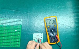
The Relationship Between PCB Design, Manufacturing, and Capacitor Reliability
Reliable capacitor performance begins before the PCB reaches the testing stage.
During PCB Design, engineers need to consider capacitor placement, electrical characteristics, voltage rating, ripple-current capability, thermal conditions, package size, and return-current paths.
For example, high-frequency decoupling capacitors should generally be placed close to the relevant IC power and ground connections to minimize parasitic inductance. Power-filtering capacitors may require adequate copper area and appropriate thermal considerations.
During PCB Manufacturing and PCB Assembly, soldering temperature, reflow profiles, component placement, solder-joint quality, contamination, and inspection can affect component reliability.
For this reason, capacitor troubleshooting should not be considered independently from the complete PCB development and manufacturing process.
A professional manufacturer such as Kingda can support engineers by considering manufacturability, component placement, assembly requirements, inspection, and testing during the PCB production process.
When Should a Capacitor Be Replaced?
A capacitor may need replacement when:
- Its measured capacitance is outside the specified tolerance.
- ESR is significantly higher than the expected range.
- Leakage current is excessive.
- The component is visibly swollen, cracked, burned, or leaking.
- The capacitor causes abnormal ripple or transient behavior.
- Its electrical performance changes significantly under operating conditions.
- The component has experienced excessive voltage or temperature stress.
Before replacing a capacitor, verify its capacitance, voltage rating, polarity, package, temperature rating, ESR characteristics, ripple-current rating, and other application-specific requirements.
The replacement component should not be selected based only on capacitance value.
Conclusion
Learning how to test a capacitor on a PCB is an important PCB Troubleshooting skill for engineers, technicians, and electronics manufacturers. Visual inspection can identify obvious physical damage, while a multimeter can provide basic electrical screening. ESR meters are particularly useful for evaluating electrolytic capacitors, while oscilloscopes can reveal ripple and dynamic behavior that simple static measurements may miss. An LCR meter provides more detailed component characterization when greater accuracy is required.
The key challenge is that PCB capacitor testing performed in-circuit can be influenced by surrounding components. Therefore, measurements should always be interpreted in the context of the complete circuit and the manufacturer’s specifications. When necessary, the capacitor can be removed for confirmation.
Proper capacitor testing can reduce unnecessary component replacement, speed up fault diagnosis, and help protect the PCB from avoidable rework damage. By combining systematic PCB Design, PCB Manufacturing, assembly, inspection, and troubleshooting practices, engineers can improve both circuit reliability and maintenance efficiency.