Automotive PCB: PCB Design, PCB Manufacturing & Automotive Electronics Guide
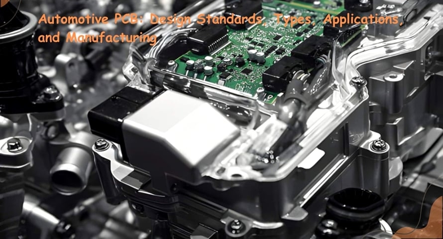
Modern vehicles are no longer simply mechanical machines. They have evolved into sophisticated “computers on wheels,” integrating hundreds of electronic control units, sensors, communication systems, and power-management circuits. At the center of this transformation is the Automotive PCB, which provides the electrical and mechanical foundation for many critical automotive electronic systems.
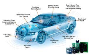
From engine and transmission control to battery management, infotainment, radar, and advanced driver assistance systems (ADAS), automotive PCBs must deliver stable performance under vibration, temperature fluctuations, moisture, chemicals, and long operating lifecycles.
This article explains what automotive PCBs are, their major types, PCB Design requirements, manufacturing processes, applications, benefits, challenges, cost factors, and future trends.
What Is an Automotive PCB?
An automotive PCB is a printed circuit board specifically designed and manufactured for electronic systems used in vehicles. Unlike many consumer-electronics PCBs, automotive circuit boards may need to operate reliably under severe environmental and mechanical conditions.
Depending on the application, an automotive PCB may be exposed to:
- High and rapidly changing temperatures
- Mechanical vibration and shock
- Humidity and condensation
- Automotive fluids and chemical contaminants
- Electrical transients and voltage fluctuations
- Electromagnetic interference (EMI)
- Long-term thermal cycling
- High current and power density
Automotive PCB applications range from relatively simple body-control electronics to safety-critical systems and high-power EV platforms. Therefore, the required material system, layer structure, copper thickness, surface finish, testing, and reliability qualification depend heavily on the specific vehicle application.
Types of Automotive PCBs
Different automotive systems require different PCB technologies. The most common types include rigid PCBs, flexible PCBs, rigid-flex PCBs, HDI PCBs, and metal-core PCBs.
Rigid Automotive PCB
Rigid PCBs use a mechanically stable substrate and are widely used where the circuit board does not need to bend during operation.
Typical applications include:
- Engine control electronics
- Body control modules
- Instrument clusters
- Infotainment systems
- Transmission control units
- Gateway modules
FR-4 remains a common material platform, while high-Tg or specialized laminates may be selected when greater thermal or electrical performance is required.
Flexible Automotive PCB
Flexible PCBs are manufactured using flexible materials such as polyimide and are useful where space is restricted or the circuit must accommodate movement.
Typical applications include:
- Door electronics
- Steering-wheel electronics
- Display connections
- Instrument panels
- Lighting assemblies
- Compact sensor modules
Flexible circuits can reduce wiring complexity and help engineers route electrical connections through difficult mechanical spaces.
Rigid-Flex Automotive PCB
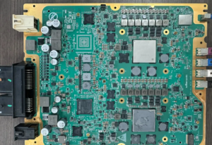
Rigid-flex PCBs combine rigid sections with flexible circuit sections in one integrated structure. This technology can reduce connectors, cable assemblies, and mechanical interfaces while improving packaging flexibility.
Rigid-flex PCBs are particularly useful when automotive electronics must fit into irregular or space-constrained assemblies.
HDI Automotive PCB
HDI PCB technology uses features such as microvias, fine lines, fine-pitch routing, and sequential build-up structures to achieve higher wiring density.
HDI technology is particularly useful for compact automotive electronics such as:
- ADAS modules
- Navigation systems
- Camera electronics
- Radar-related electronics
- Communication modules
- Advanced infotainment systems
The exact HDI structure should be determined according to signal-integrity requirements, component density, manufacturability, and reliability requirements.
Metal-Core PCB
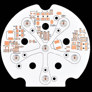
Metal-core PCBs, including aluminum-based PCBs, provide an efficient thermal path for applications that generate significant heat.
They are commonly considered for:
- Automotive LED lighting
- Power electronics
- DC/DC converters
- Motor-control electronics
- High-power modules
The metal core helps transfer heat away from high-power components, although the complete thermal design still depends on copper distribution, dielectric thermal resistance, vias, interfaces, and the mechanical heat sink.
Automotive PCB Design Requirements
Automotive electronics must operate reliably in demanding environments. Consequently, Automotive PCB Design requires more than simply routing signals between components.
Thermal Management
Power components generate heat during operation, and excessive temperature can accelerate component aging and reduce PCB reliability.
Automotive PCB thermal design may include:
- Thermal vias
- Copper planes
- Heavy copper traces
- Heat spreaders
- Metal-core constructions
- External heat sinks
- Optimized component placement
Thermal simulation and temperature-rise analysis can help engineers identify potential hot spots before production.
Vibration and Mechanical Reliability
Automotive electronics are exposed to continuous vibration and mechanical shock. Component placement, PCB mounting, solder-joint design, connector selection, and mechanical support must therefore be considered together.
Large and heavy components may require additional mechanical reinforcement. Flexible sections also require appropriate bend-radius and strain-relief design.
EMI/EMC Control
Automotive systems contain high-speed digital circuits, switching power supplies, motors, wireless communication systems, and other potential noise sources.
Effective EMI/EMC design may include:
- Continuous reference planes
- Controlled return paths
- Appropriate grounding strategies
- Short high-current loops
- Shielding where necessary
- Filtering and decoupling
- Controlled impedance routing
- Careful separation of noisy and sensitive circuits
EMC performance should be considered from the beginning of the PCB design process rather than treated as a final-stage correction.
Trace Width and Spacing
Trace width must be selected according to current, allowable temperature rise, copper thickness, conductor geometry, and the PCB construction.
IPC guidance such as IPC-2152 can be used as part of the engineering process, but a single trace-width value should not be treated as universally applicable to every automotive PCB.
High-voltage automotive applications also require appropriate creepage and clearance distances based on the applicable electrical requirements, working voltage, pollution conditions, insulation system, and product standard.
Signal Integrity
Modern automotive systems increasingly rely on high-speed interfaces and high-frequency sensors.
For these designs, engineers may need to consider:
- Controlled impedance
- Differential-pair routing
- Return-path continuity
- Crosstalk
- Via transitions
- Connector performance
- Stackup configuration
- Dielectric properties
- Transmission-line effects
This becomes especially important for automotive Ethernet, radar-related circuits, high-speed camera interfaces, and other high-data-rate systems.
Automotive PCB Standards and Certifications
Automotive PCB production requires a structured quality-management and reliability approach. Several standards and specifications may be relevant depending on the product, customer, and application.
IATF 16949
IATF 16949 is an automotive quality management system standard focused on quality and continual improvement throughout the automotive supply chain.
It is highly relevant when supplying PCB products to automotive manufacturers and automotive component suppliers.
ISO 26262
ISO 26262 addresses functional safety for road vehicles. It provides a framework for managing risks associated with electrical and electronic systems throughout the relevant product lifecycle.
Importantly, ISO 26262 is not simply a “PCB certification.” Its requirements apply to the development and safety lifecycle of automotive electrical and electronic systems.
IPC-6012DA
IPC-6012DA is an automotive application addendum associated with rigid printed boards and provides additional requirements relevant to automotive PCB applications.
The exact requirements applicable to a project should be determined according to the required PCB classification and customer specifications.
AEC-Q100 and AEC-Q200
AEC-Q100 and AEC-Q200 are qualification specifications for automotive electronic components.
AEC-Q100 primarily addresses integrated circuits, while AEC-Q200 applies to passive electronic components. They are therefore component qualification standards rather than PCB manufacturing certifications.
For an automotive PCB project, the PCB itself and the components assembled onto it may be subject to different qualification requirements.
Automotive PCB Manufacturing Process
A controlled PCB Manufacturing process is essential for achieving consistent quality and reliability.
1. Material Selection
Material selection is one of the first major decisions in automotive PCB manufacturing.
Depending on the application, manufacturers may use:
- Standard FR-4
- High-Tg FR-4
- Low-loss/high-frequency laminates
- Flexible polyimide materials
- Metal-core substrates
- Heavy-copper constructions
- Specialized automotive-grade laminate systems
Material selection should consider temperature, CTE, dielectric properties, moisture resistance, mechanical requirements, copper thickness, and expected service life.
2. Imaging and Etching
The imaging process transfers the designed circuit pattern onto the PCB material.
After imaging, unwanted copper is removed during etching, leaving the required conductive pattern.
For high-density automotive PCBs, manufacturing capability must be carefully matched to the required line width, spacing, registration accuracy, and layer-to-layer alignment.
3. Lamination
For multilayer PCBs, individual copper and dielectric layers are bonded together under controlled temperature and pressure.
A stable lamination process is critical for:
- Layer registration
- Dielectric thickness
- Mechanical stability
- Via reliability
- Thermal performance
- Overall PCB dimensional stability
For advanced HDI constructions, sequential lamination may be required to create build-up layers and microvia structures.
4. Drilling and Via Formation
Drilling creates through-holes, while laser drilling may be used for microvias in HDI designs.
Depending on the PCB structure, manufacturing may involve:
- Mechanical drilling
- Laser drilling
- Through vias
- Blind vias
- Buried vias
- Filled and capped microvias
Via design must be coordinated with the stackup and manufacturing process to ensure reliable plating and long-term durability.
5. Copper Plating
After drilling, exposed hole walls require metallization and copper plating to establish electrical connections between PCB layers.
For automotive applications, plating thickness, uniformity, adhesion, and via reliability are important quality-control considerations.
6. Surface Finish
Common surface finishes include:
- ENIG
- HASL
- OSP
- Immersion tin
- Immersion silver
- ENEPIG
The appropriate finish depends on soldering requirements, storage conditions, contact requirements, component pitch, corrosion resistance, and product lifecycle.
ENIG is often attractive for fine-pitch assemblies because it provides a relatively flat surface, while other finishes may be more appropriate depending on cost and application requirements.
7. Solder Mask and Silkscreen
Solder mask protects copper surfaces and helps reduce the risk of solder bridging during assembly.
Silkscreen is used for reference designators, polarity marks, identification codes, and other manufacturing or service information.
For automotive electronics, clear identification and traceability can be particularly useful during assembly, inspection, repair, and lifecycle management.
8. Electrical and Quality Testing
Automotive PCB manufacturing commonly incorporates multiple inspection and testing methods depending on the product.
These may include:
- AOI
- Automated electrical testing
- Flying-probe testing
- ICT
- X-ray inspection
- Dimensional inspection
- Impedance testing
- Microsection analysis
- Thermal or environmental testing
No single inspection method can detect every possible defect. A combination of fabrication inspection, electrical testing, assembly inspection, and functional testing may therefore be required.
Applications of Automotive PCBs
Automotive PCBs are used throughout modern vehicles, from basic body electronics to high-voltage EV power systems.
Powertrain Electronics
Powertrain electronics may include:
- Engine control units
- Transmission control units
- Motor controllers
- Inverter electronics
- Power-management circuits
These systems can require high thermal performance, reliable power delivery, accurate sensing, and strong EMC control.
Safety Systems
Automotive PCBs are critical components in many safety-related systems, including:
- Airbag control systems
- ABS
- Electronic stability control
- ADAS
- Electronic braking systems
Safety-related electronics generally require rigorous design verification, validation, traceability, and system-level functional-safety processes.
Body Electronics
Body-control electronics are used for functions such as:
- Power windows
- Door modules
- Mirror control
- Climate control
- Lighting
- Seat control
- Central locking
These applications often emphasize compact design, cost efficiency, reliability, and resistance to environmental exposure.
Infotainment and Connectivity
Modern vehicles incorporate increasingly sophisticated infotainment and communication functions.
Automotive PCBs can be found in:
- Navigation systems
- Digital instrument clusters
- Bluetooth modules
- Wireless communication systems
- Touchscreen displays
- Automotive Ethernet systems
- Telematics modules
These systems place greater demands on high-speed signal integrity and electromagnetic compatibility.
Electric and Hybrid Vehicles
EVs and HEVs have significantly increased the importance of automotive power electronics.
PCBs can be used in:
- Battery management systems
- Inverters
- On-board chargers
- DC/DC converters
- Motor-control systems
- Charging systems
- High-voltage monitoring circuits
These applications may require thicker copper, enhanced thermal management, high-voltage insulation design, and carefully controlled creepage and clearance.
Benefits of Automotive PCB Manufacturing
1. Improved Vehicle Reliability
A properly designed and manufactured automotive PCB can provide stable electrical performance throughout repeated temperature cycles, vibration exposure, and long operating periods.
This reliability is particularly important for systems involved in braking, power management, vehicle control, sensing, and communication.
2. Miniaturization and Space Efficiency
Modern vehicles contain more electronic functions while available installation space remains limited.
HDI PCB technology, flexible circuits, and rigid-flex designs can help integrate more functionality into smaller assemblies.
3. Improved Energy Efficiency
In EV and hybrid applications, PCB design directly affects power distribution, sensing, switching, and thermal performance.
Optimized copper distribution, short current paths, appropriate component selection, and effective thermal management can reduce electrical and thermal losses.
Flexible and rigid-flex circuits can also reduce some wiring and connector requirements in suitable applications, although the actual weight and cost benefits depend on the vehicle architecture.
4. Advanced Thermal Management
Automotive power electronics can generate significant heat.
Heavy copper, thermal vias, metal-core PCB structures, copper planes, heat spreaders, and mechanical cooling solutions can work together to improve thermal performance.
5. Integration of Advanced Driver Assistance Systems
ADAS depends on multiple sensors and electronic processing systems.
Automotive PCBs support systems involving:
- Radar
- Cameras
- LiDAR
- Ultrasonic sensors
- Vehicle networking
- Sensor processing
- Control units
High-speed PCB design becomes increasingly important as sensor resolution, data rates, and processing requirements increase.
Challenges in Automotive PCB Manufacturing
Zero-Defect Expectations
Automotive electronics are subject to stringent quality requirements, especially when PCB assemblies are used in safety-related systems.
Rather than interpreting “zero defects” as literally eliminating every possible manufacturing variation, automotive production typically relies on robust process control, defect prevention, inspection, traceability, and corrective-action systems.
Miniaturization
More sensors, processors, communication interfaces, and power electronics must fit into increasingly compact vehicle architectures.
This drives demand for:
- Fine-line PCB technology
- HDI
- Microvias
- Advanced stackups
- High-density component placement
- Rigid-flex solutions
Long Service Life
Automotive electronics are expected to remain functional over long vehicle lifecycles.
PCB reliability must therefore account for:
- Thermal cycling
- Humidity
- Vibration
- Mechanical stress
- Copper fatigue
- Via reliability
- Solder-joint fatigue
- Material degradation
- Corrosion
Reliability testing should reflect the actual application environment rather than relying on a single generic test.
Complex Supply-Chain Requirements
Automotive programs often require detailed documentation, traceability, change management, process control, and long-term component availability.
A PCB manufacturer must therefore support not only fabrication quality but also engineering communication and supply-chain consistency.
Automotive PCB Manufacturing Cost Factors
The cost of an automotive PCB depends on its electrical, mechanical, thermal, and reliability requirements.
Material
Standard FR-4 may be sufficient for some applications, while high-Tg, low-loss, flexible, metal-core, or specialized laminate systems can increase material costs.
Layer Count
Increasing the number of layers generally increases fabrication complexity and material consumption.
HDI structures with sequential lamination and microvias can further increase manufacturing cost.
Copper Thickness
High-current automotive and EV power applications may require heavier copper.
Greater copper thickness increases material consumption and can also affect etching, plating, thermal management, and manufacturing tolerances.
Testing Requirements
Advanced inspection and reliability testing can increase production costs, but the appropriate test strategy depends on product risk, customer requirements, and application.
Board Size and Geometry
Large boards, unusual shapes, tight tolerances, castellations, slots, edge requirements, and complex mechanical features can increase manufacturing complexity.
Production Volume
Prototype, low-volume, and mass-production pricing can differ significantly because setup, engineering, tooling, testing, and production efficiency are distributed differently across order quantities.
Future Trends in Automotive PCB Technology
High-Voltage EV PCBs
The transition toward EVs is increasing demand for PCB technologies capable of supporting high-power and high-voltage electrical systems.
Modern EV architectures commonly use high-voltage battery systems, including platforms around 400 V and 800 V. The exact voltage depends on the vehicle architecture.
Future automotive PCBs will increasingly emphasize:
- Heavy copper
- High-current routing
- Thermal management
- Electrical insulation
- Creepage and clearance
- High-voltage sensing
- Reliable power conversion
ADAS and High-Frequency Signal Integrity
As ADAS systems become more sophisticated, automotive electronics must process increasingly large amounts of sensor data.
Radar systems operate at high frequencies and require carefully controlled PCB materials and transmission-line structures. High-resolution cameras, LiDAR, and other sensors also increase the demand for high-speed data interfaces.
This trend is driving greater interest in:
- Low-loss materials
- Controlled impedance
- Fine-line routing
- HDI
- Advanced multilayer stackups
- Improved EMI/EMC design
Automotive Ethernet and High-Speed Networking
Modern vehicles are increasingly adopting high-speed automotive networking architectures.
Automotive Ethernet and other high-speed communication technologies require careful attention to differential-pair routing, impedance control, return paths, connector transitions, and EMC performance.
Greater Integration
Future vehicle electronics are expected to consolidate more functions into centralized or zonal architectures.
This may increase demand for high-density PCBs, high-speed interfaces, thermal management, power electronics integration, and advanced rigid-flex solutions.
Why Choose Kingda for Custom Automotive PCB Manufacturing?
For automotive PCB projects, selecting a manufacturer should involve more than comparing unit prices. Engineers and procurement teams should evaluate manufacturing capability, quality systems, engineering support, testing, traceability, material control, and experience with the required PCB technology.
Kingda can support automotive PCB projects with a focus on engineering-driven PCB Manufacturing, including solutions for applications that require:
- Multilayer PCB fabrication
- HDI and microvia structures
- Heavy-copper PCB technology
- High-Tg materials
- Flexible and rigid-flex PCBs
- Thermal-management solutions
- High-density circuit design
- Controlled-impedance structures
- Automotive PCB inspection and testing
For a specific automotive project, the required specifications should be established from the vehicle system architecture, PCB drawings, stackup, materials, reliability requirements, applicable standards, and customer quality requirements.
How to Choose an Automotive PCB Manufacturer
When selecting an automotive PCB supplier, consider the following factors:
1. Automotive Quality Management
Check whether the manufacturer has an automotive-oriented quality management system and can provide the documentation required by your supply chain.
2. Manufacturing Capability
Confirm whether the supplier can manufacture your required:
- Layer count
- Copper thickness
- HDI structure
- Microvia
- Flexible or rigid-flex structure
- Material system
- Surface finish
- Controlled impedance
3. Testing and Inspection
Ask about AOI, electrical testing, X-ray, impedance testing, microsection analysis, reliability testing, and other inspection capabilities relevant to the product.
4. Traceability
Automotive programs may require detailed traceability for materials, production batches, inspection results, and engineering changes.
5. Engineering Support
A capable supplier should be able to conduct DFM analysis and identify potential manufacturing risks before production.
6. Long-Term Supply Capability
Automotive products can remain in production for many years. Therefore, material availability, process stability, engineering-change management, and production continuity should be considered during supplier selection.
Conclusion
Automotive PCBs have become a fundamental part of modern vehicle electronics. From engine control and braking systems to ADAS, infotainment, battery management, and EV power electronics, PCBs provide the electrical infrastructure required for increasingly sophisticated vehicles.
As vehicles become more electrified, connected, and automated, automotive PCB technology is moving toward higher density, higher power, higher frequency, better thermal management, and stronger reliability requirements.
A successful automotive PCB project requires close coordination between PCB Design, materials engineering, PCB Manufacturing, assembly, testing, and system-level validation. Choosing a manufacturing partner with the appropriate technical capabilities and quality-management processes can help engineers develop PCB assemblies that meet the electrical, mechanical, thermal, and reliability requirements of their target vehicle application.
Article Summary
Automotive PCBs are specialized circuit boards designed for the demanding electrical and environmental conditions found in modern vehicles. They can include rigid, flexible, rigid-flex, HDI, and metal-core constructions. Key design considerations include thermal management, vibration resistance, EMI/EMC control, signal integrity, trace width, spacing, and high-voltage insulation.
Automotive PCB applications cover powertrain systems, safety electronics, body control, infotainment, ADAS, BMS, EV inverters, and charging systems. As EV, ADAS, automotive Ethernet, and centralized vehicle architectures continue to develop, the demand for reliable and high-performance automotive PCB technology is expected to continue evolving.