Backdrilling: Controlling Via Stubs
The Stub Problem
A through via connects the layers it is meant to connect, but it also continues to the opposite side of the board as an unused length of plated barrel. That unused length is the stub, and electrically it behaves as an open-ended transmission line hanging off the signal path. At low frequencies it is invisible. As the data rate rises, the stub resonates at a frequency set by its length and the dielectric constant, and at that resonance the signal energy is reflected rather than transmitted. The result is a deep notch in the insertion loss and a distortion of the eye diagram that no amount of equalisation can fully repair. Backdrilling removes the stub.
How Backdrilling Works
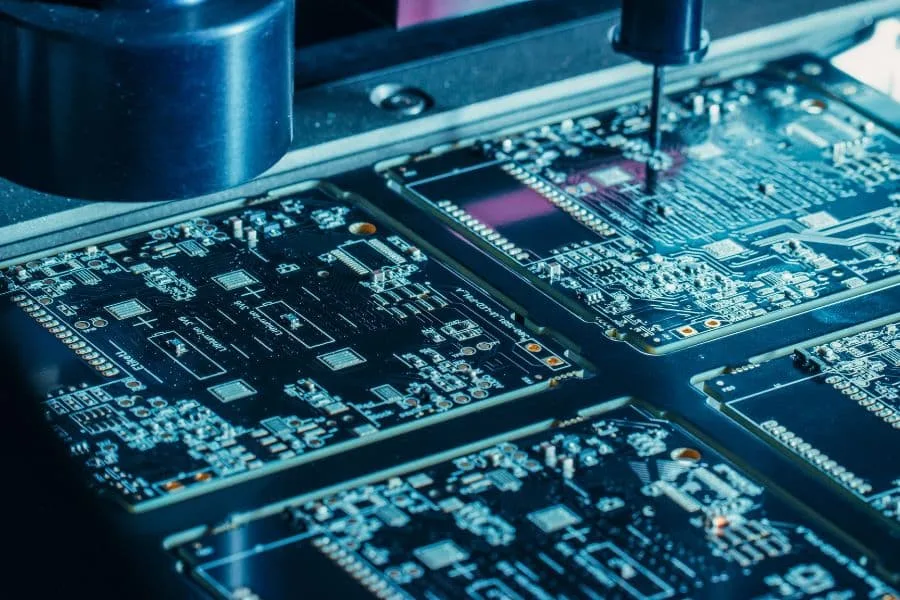
After the board is plated and the outer layers are complete, a drill bit of larger diameter than the original via is used to re-enter the hole from the side that does not carry the signal, cutting away the plated barrel down to a controlled depth. The bit does not need to be precise in diameter because it only removes the barrel; what must be precise is how far it goes. The remaining barrel between the deepest connected layer and the new bottom of the hole is the residual stub, and that is the number the process is measured on. A typical specification is a residual stub of no more than 8 to 10 mils, with tighter targets on very high speed designs.
Stub Length and Frequency
The quarter-wave resonance of a stub falls as the stub gets longer and as the dielectric constant rises. A rough working figure for a conventional laminate is that a stub of about 60 mils resonates near 10 GHz, so a 20 mil stub pushes the notch well above the working band. This is why backdrilling appeared first on thick backplanes, where a through via can be 150 mils or more, and why it has spread into thinner boards as serial data rates have climbed. The useful way to set the target is to compute the stub length at which the notch falls outside the band of interest, then to specify a residual stub comfortably below it rather than to a round number.
Depth Tolerance on the Drawing
Backdrilling is a depth-controlled operation, so the drawing has to define the depth and its tolerance and, more importantly, the definition of the measurement. The convention is to specify the residual stub, measured from the bottom of the last connected layer to the new bottom of the hole, rather than the depth of the cut, because the cut depth depends on the board thickness. The tolerance has to allow for both the drill depth repeatability and the layer position variation in the stack. Where the stack has a tight layer-to-layer registration, a tighter stub tolerance is achievable; where the registration is loose, the specification should leave more material rather than risk cutting into a connected layer.
Drill Size and What It Touches
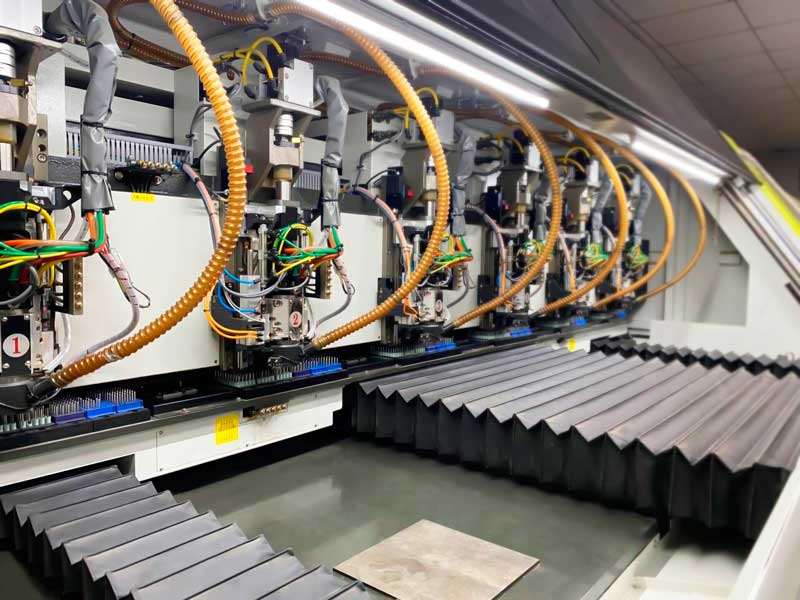
The backdrill bit is larger than the via, so it removes the pad on the entry side along with the barrel. That means the entry side must not carry a component pad or a signal that needs the surface copper, and the design has to reserve the area around the via for the larger bit. The bit also has to clear the antipads of the layers it passes through, which affects the plane clearance around every backdrilled via. Where several backdrilled vias sit close together, the enlarged clearance can cut the plane into narrow necks, so the layout should group backdrilled vias and give the plane room to remain continuous around them.
Effect on Manufacturing and Yield
Backdrilling adds a drill step that happens after plating, which is late in the process and therefore expensive if it goes wrong. The failure mode that matters is cutting into a connected layer, which opens a net that was already tested. Because the operation is performed on a finished panel, the shop normally verifies depth on a coupon or by measuring a sample hole before running production. A second pass to clean the hole and a check that the barrel is fully removed complete the process. All of this adds cost, so backdrilling should be applied only to the vias that need it rather than to an entire board.
When It Is Worth It
Backdrill where a thick board carries high-speed signals through long vias and the stub would otherwise create a notch inside the working band. Do not backdrill power and ground vias, low-speed signals or vias whose stub resonance is far above the band. Where the stub is short enough that the resonance is out of band, the money is better spent on the stack-up or on connector selection. The decision should be made from a channel simulation with the actual stub length rather than from a general rule, because the answer depends on the data rate, the laminate and the via length together.
Coupons and Verification
Because backdrilling happens late, the panel should carry a coupon that allows the stub to be measured directly. A coupon with the same via length and layer arrangement as the product, sectioned after backdrilling, is the only way to confirm what the process actually achieved rather than what the depth readout suggests. Where the product will be characterised for insertion loss, the coupon can also be patterned as a test line so that the loss is measured on the same geometry that carries the signal. The two measurements together, a physical stub length and an electrical loss curve, are what turn a backdrill specification into a controlled process rather than an instruction. Shops that run this check routinely will also report the residual stub statistics, which is a useful signal of how well their depth control actually holds on a given stack.

FAQ
What is backdrilling? Re-drilling a plated through via from one side with a larger bit to remove the unused part of the barrel, known as the stub.
What is a good residual stub? Typically 8 to 10 mils, with tighter targets for very high data rates, specified as the residual rather than the cut depth.
Why does the stub matter? It resonates like an open transmission line and creates a notch in the insertion loss at a frequency set by its length.
Does backdrilling remove the pad? Yes, on the entry side, so that side must not carry a pad or a signal that needs the surface copper.
Can I backdrill after assembly? No. It is performed during fabrication, after plating and before the final finish, on the panel.
Conclusion
Backdrilling is a depth-controlled operation aimed at one electrical problem, so it should be specified where that problem exists and nowhere else. Compute the stub length that moves the notch out of band, specify the residual stub and its tolerance on the drawing, reserve clearance for the larger bit and group the vias so the planes stay continuous. The via structures involved are described under PCB capabilities, the drilling sequence belongs to PCB manufacturing, and the impedance and layer planning that decides which vias need it is part of PCB design and layout. High-speed boards of this type are normally characterised during a prototype PCB assembly build in 2026.