Bare Board Test Strategy for Electrical Continuity Checks
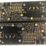
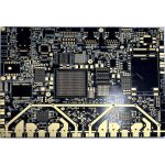
A bare board test is an electrical check carried out on the board before any components are fitted, and it exists to catch the faults that no amount of visual inspection can find. The board is finished at that point, with all its copper, holes and surface finish in place, so a fault found here is a fabrication fault and can be repaired or the panel can be scrapped before value is added.
What a Bare Board Test Proves
The test proves that every net is continuous and that no two nets are connected. In practice that means measuring resistance between points that should be joined and confirming a very high resistance between points that should be isolated, across every hole and every pad on the board.
It does not prove impedance, it does not prove that the copper is thick enough and it does not prove that the board will work in the field. Those properties are controlled elsewhere, which is why the electrical test is one of several checks rather than a substitute for all of them.
<img src="https://www.gopcba.com/wp-content/uploads/2020/12/service_03.jpg" alt="Flying probe machine testing a bare printed circuit board panel” />
Open and Short Circuits: The Two Primary Defects
An open circuit is a break in a net, usually caused by a drilled hole that did not plate correctly, an etching fault that thinned a trace until it parted or a crack at the wall of a via. It shows as a resistance far above the expected value, and it may only appear after thermal cycling. A continuity test that reports a value just inside the limit deserves a second look, because a marginal connection will drift out of specification as the board is handled and soldered. The plating quality behind that reading is covered in the guide to plated hole copper.
A short circuit is an unwanted connection, produced by residual copper between traces, by a conductive particle trapped in the laminate or by a plating bridged across a narrow gap. A short is the more dangerous of the two, because it can pass a functional test at low power and then fail when the board carries current.
Flying Probe Testing
A flying probe machine carries a small number of moving heads, each fitted with a fine needle, and it visits the test points one pair at a time. Because the needles move, the machine needs no fixture, so it can be programmed from the CAD data and used for a single board as easily as for a batch.
The trade off is speed. Every measurement costs a movement, so a dense board can take many minutes, and the number of heads limits how much of that time can be recovered. Needle wear is a second factor, since each contact removes a little material from the tip, so the probe pressure and the number of touchdowns are controlled and the needles are replaced on a schedule. The method is most valuable for prototypes, for small batches and for boards that will never justify the cost of a dedicated fixture.
Fixture and Bed of Nails Testing
A fixture carries a pin for every test point, mounted in a plate that is drilled to match the board. When it is pressed down, all the points are contacted at once, so the whole board can be tested in seconds rather than minutes.
The fixture is expensive to make and its cost is fixed, so the method only makes sense when the volume is high or when the same board will be produced repeatedly. It also demands that test points are placed on a regular grid and kept clear of tall features, because the pins must reach the pad without being blocked. A pin that is obstructed, or that lands on the edge of a pad, returns a reading that looks like a fault, and the false failures that follow cost more production time than the fault would have done.
Test Coupons and Their Role
A coupon is a small test pattern built onto the production panel alongside the boards, and it carries the same features as the product in a form that is easy to measure. It is used for the checks that cannot be done on a finished board, such as the resistance of a plated hole or the impedance of a controlled trace.
Because the coupon is made in the same process as the boards, its results represent the process rather than the individual board, and the assumption is that the panel that produced a good coupon produced good boards. The coupon design is described in more detail in the guide to test coupon design.
Design Rules That Make Boards Testable
Test access has to be designed in, because a net that cannot be contacted cannot be tested. The usual rules set a minimum size for the test pad, a minimum distance between pads and a keep out around each pad so that the needle lands flat and does not slip onto a neighbour.
Vias are the most convenient test points, and leaving the mask off a via costs nothing at the design stage. The same via usually serves the assembly process as well, so the test access often comes at no extra cost at all. Where a net is buried and has no via on the surface, the designer has to decide whether to add one for test or to accept that the net will be covered by other means.
Test Coverage, Nets and Access
Coverage is the proportion of the nets that the program can actually reach, and it is almost never one hundred percent on a dense board. Nets that are tied to a plane, nets that share a node with many others and nets that are simply too short to probe are the usual gaps.
The gaps must be listed and accepted rather than ignored, because a customer who is told the coverage was complete will assume that the untested nets do not exist. The remaining risk is then managed by the coupon, by the process controls and by the inspection steps that run in parallel.
Test Data, Reporting and Traceability
The output of the test is a data file that lists every net, the measured value and the result. That file is the evidence that the board was tested, and it should be stored with the panel identity so that a fault found later can be traced back to the process that produced it.
The value of the record is not only in the pass or fail decision. A net whose resistance creeps upward over a batch is telling the process engineer something about hole plating long before it fails, and that trend is only visible when the data is kept and reviewed.
Choosing a Test Strategy
The choice comes down to volume, density and timescale. A prototype with a short deadline is usually tested by flying probe, a production board with a stable design is usually tested on a fixture, and boards with very fine pitch or unusual geometry may need both at different stages.
Whichever method is used, the test should be specified at the design stage and not added at the end of the order, because the access, the panel layout and the data format all have an effect on what the fabricator can measure. The wider sequence of fabrication steps is set out in the guide to PCB production.
FAQ
Is a bare board test the same as a functional test? No. The bare board test checks continuity and isolation on an unpopulated board, while a functional test checks that the assembled product behaves as intended.
Can every board be tested by flying probe? Yes, in principle, since no fixture is needed. The limit is time and cost rather than capability, and a very dense board can take long enough that a fixture becomes the cheaper option.
What happens when a board fails the test? The fault is located from the data, then the board is either repaired and retested or scrapped. A repeated failure at the same net usually points to a process fault rather than to a single board.