EV Battery Protection Board: BMS Layout and Isolation
Every electric vehicle carries a board whose only job is to decide whether the battery is allowed to deliver current. The battery protection board sits between the pack and the vehicle, it monitors the voltage, the current and the temperature, and it opens the contactors when any of those leaves the permitted window.
Because a failure of that decision is a safety event rather than a functional one, the board is designed with constraints that do not apply elsewhere: isolation distances, redundancy, diagnostics and a documented failure response.
What the Protection Board Does
The board measures the pack current, the cell or module voltages and the temperatures, evaluates the state of the pack against the limits and commands the contactors. It also manages the precharge sequence, handles the insulation monitoring signal and reports its status to the vehicle controller.
Its own power supply comes from the pack, so the board has to survive the full pack voltage on its input and remain functional across the entire state of charge. That requirement shapes the input protection and the isolation of every interface.
Current Path and Shunt Sensing
Current is measured either by a shunt resistor in the main path or by a magnetic sensor around it. A shunt is simple and accurate but dissipates power, and at several hundred amperes the dissipation is significant: a 0.1 milliohm shunt carrying 400 A produces 16 W, which has to leave the board.
The measurement circuit is a precision differential amplifier across the shunt, and its layout decides the accuracy. The sense traces are a Kelvin pair taken from inside the shunt terminals, routed as a matched pair back to the amplifier with the filter close to the input pins, and kept away from the switching noise of the contactor drive.
Precharge and Contactor Control
Closing the main contactor onto an uncharged inverter capacitance produces an inrush current that can weld the contacts. The precharge circuit charges that capacitance through a resistor before the main contactor closes, and the board sequences the two events with a defined delay.
The contactor coils are inductive loads driven from a low voltage supply, and they generate a large flyback transient when they open. The drive circuit includes the suppression, and the routing keeps the coil current loop physically small so that the transient does not couple into the measurement circuits.
Isolation and Creepage
The measurement side, the low voltage logic and the pack side are separated by isolation barriers. The distances are set by the working voltage and by the applicable standard, and they dominate the layout of a board that has to hold several hundred volts between adjacent regions.
Slots milled through the board, wide spacing around the isolation components and a clear demarcation between the two ground systems are all part of the design. Where the barrier is crossed by a signal, the isolator is placed so that the barrier line is continuous rather than zigzagging between components.
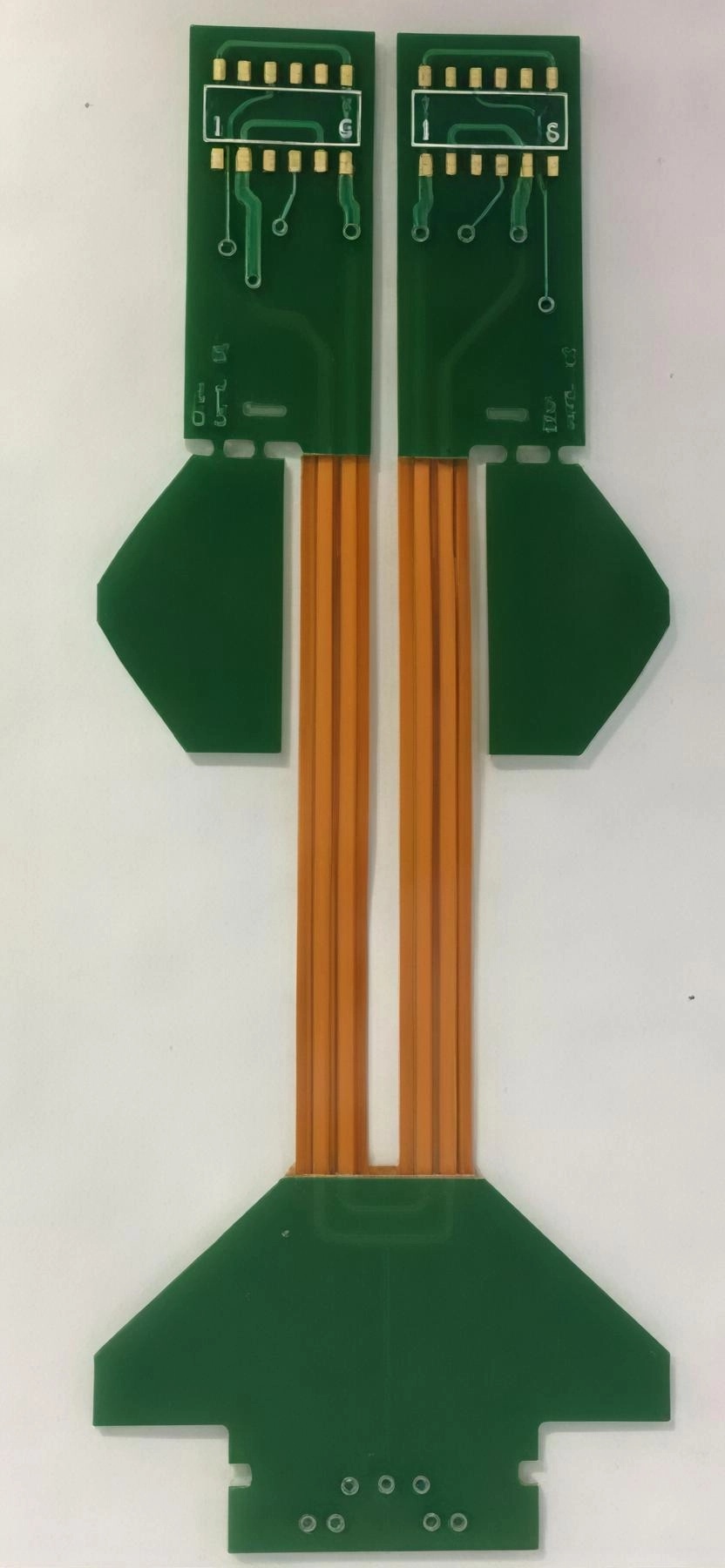
<img src="https://www.gopcba.com/wp-content/uploads/2026/08/24-layer-pcb-1536×640-1.webp" alt="BMS board showing isolated cell monitoring interface” />
Cell Monitoring Interface
The cell monitoring system reports voltages through a daisy chained or isolated communication bus, and the board is the point where that bus meets the pack level logic. The interface has to tolerate the potential difference between the two domains and to survive a broken connection without producing a false reading.
Filtering on the bus is a balance. Enough filtering to reject the switching noise of the inverter, but not so much that the propagation delay of a safety critical message becomes unacceptable. The capacitors on an isolated bus are also a leakage path, and their value is limited by the insulation monitoring requirement.
Thermal Load and Copper
The board carries the shunt current, the contactor coil current and the losses of its own power supply. The copper weight on the main path is chosen for the continuous current and for the permitted temperature rise, and the shunt is mounted so that its heat spreads into the copper rather than into the amplifier beside it.
The thermal design also has to consider the enclosure. A protection board usually sits in a metal housing with limited airflow, so the copper area, the thermal interface to the housing and the position of the temperature sensitive components relative to the warm areas are all part of the layout review.
Diagnostics and Fault Handling
A protection board is expected to detect its own failures. Plausibility checks compare the current measurement against a second source, the contactor state is confirmed by a feedback contact, and the measurement chain is tested at start up. The board reports the fault and its own health rather than failing silently.
That diagnostic capability has to be designed in. Test points on the measurement chain, a reference channel that can be switched in, and a microcontroller with a watchdog and a safe state are the usual building blocks, and they should be reviewed against the failure modes the product is expected to handle.
Reliability and Standards
The board lives in a vibrating, thermally cycled environment and it must not produce a hazard when it fails. That leads to a design with generous creepage, components qualified for the temperature range, connectors with positive locking and a documented safe state for every credible fault.
gopcb builds these boards with heavy copper, thick dielectric for the isolation distances, controlled impedance for the communication interfaces and the documentation that an automotive qualification programme requires.
Layout Practice Around the Contactor Drive
The contactor drive is the noisiest circuit on the board and it lives beside the most sensitive. A coil that switches several amperes generates a magnetic field that a shunt amplifier can pick up, and the flyback transient when it opens couples capacitively into any trace that runs parallel to the drive. The practical measures are physical separation, a return path that is routed directly beneath the drive trace, and a snubber or a freewheeling diode placed at the coil rather than at the driver.
The sequence of the drive signals is also a layout consideration. The precharge relay and the main contactor are commanded a defined interval apart, and the traces that carry those commands should arrive at the drivers without the skew that a long unmatched route would introduce. On a safety critical board the difference of a few microseconds in the switching order is worth designing for deliberately rather than leaving to the router.
Documentation and Qualification
The documentation for a battery protection board is part of the product. Isolation distances calculated from the working voltage, the creepage and clearance table used, the component derating applied and the failure mode analysis all have to be recorded, because the qualification process reviews the reasoning rather than the artwork alone.
The same is true of the test data. Insulation resistance measurement, a high potential test on the barrier and a functional sequence test of the precharge and contactor logic are performed on every unit or on a defined sample, and the results are kept with the serial number. gopcb supports these programmes with heavy copper capability, thick dielectric options for the isolation structure and the controlled impedance and documentation that automotive customers require.
FAQ
Why is a shunt still used for current measurement? Because it is accurate, stable and immune to external magnetic fields. The penalty is dissipation, which is managed by choosing the lowest practical resistance and by providing a thermal path.
How is the precharge resistor sized? From the inverter capacitance, the permitted inrush current and the time allowed for the precharge. The resistor has to absorb the energy of that charge without exceeding its pulse rating.
What determines the isolation distances? The working voltage, the pollution degree and the applicable standard. On a pack level board the distances are large enough that they set the layout before the circuitry does.
Related reading: trace width and current calculation, DC-DC converter layout, ground current and harmonic distortion, and mixed signal PCB design guidelines.