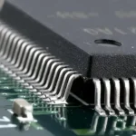
Cavity Stencil Design: 7 Rules for Step Height
A cavity stencil is a printing foil with a milled pocket that thins the metal around selected apertures, so two paste volumes can be printed in one stroke. Full thickness stays where standard pads sit, while the pocket lowers the local foil and the paste the aperture releases. Boards that mix fine pitch chips with power tabs or press fit connectors are the usual reason to order one.
The design work covers a small area but carries large consequences. Step height, pocket size, wall angle and blade support decide whether the pocket fills and releases cleanly or smears paste across the step. What follows are the numbers that matter and the checks that catch a bad pocket before the order ships.
What a Cavity Stencil Solves on a Mixed Board
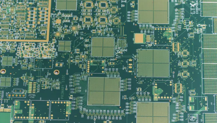
One foil thickness forces one paste volume on every aperture. That compromise holds until a pad needs three times the paste of its neighbour, which is what happens when a thermal tab or a connector sits beside 0402 chips. Thickening the whole foil to feed the large pad pushes the fine pitch apertures into bridging and slump.
The pocket breaks that link. It keeps the same stencil thickness across most of the panel and removes metal only where less paste is wanted. One print stroke, one squeegee pass and one reflow profile then serve both zones, which is why a cavity stencil is usually cheaper than splitting the print into two operations with a second foil.
How Step Height Sets the Paste Volume
Paste volume is aperture area multiplied by the depth of paste left in it, and the pocket changes only the depth. A 150 micron foil with a 50 micron pocket leaves 100 microns of paste under the blade, so volume in that window falls by about a third. The relationship stays linear, which makes the arithmetic simple once the area is known.
The trap is that a pocket also changes how paste flows into the aperture. A shallow step of 25 microns alters volume very little but still presents an edge for the blade to climb. Designers often ask for a smaller step than the process needs; 50 to 100 microns is normally visible in the deposit and still prints cleanly.
Choosing Stencil Thickness for the Base Foil
The base foil sets the volume for everything outside the pocket, so it follows from the largest aperture that has to be filled in one pass. Area ratio, the aperture opening divided by the area of its walls, should stay above 0.66 for a clean release. Below that figure paste tends to stay in the wall instead of transferring.
Once the base thickness is fixed, pocket depth is the difference between it and the thickness the fine pitch zone wants. Where that difference is more than half the base foil, the step becomes deep and the blade tends to dig into it. A second print is a better answer than a very deep pocket.
Pocket Geometry, Wall Angle and Corner Radius
The pocket wall is a ramp rather than a cliff. A vertical wall gives the squeegee a hard edge to fall off and leaves paste trapped in the corner, so most foils are machined with a tapered wall that lets the blade ride up gradually. A slope of a few degrees is enough when the step is shallow.
Corner radius matters as much as the angle. Sharp internal corners hold paste that later releases as a smear, and they concentrate stress where the foil flexes. A radius of at least 0.5 mm at each corner keeps the pocket clean and gives the step a longer life under repeated print cycles.
Machining, Etching and Laser Welding the Pocket
Chemical etching is the cheapest way to thin a region and holds depth to roughly plus or minus 15 percent, which suits steps deeper than 75 microns. Milling gives tighter depth and a defined wall angle, but it leaves tool marks that can affect release if the surface stays rough.
Laser welding builds metal up around the pocket instead of removing it, so the base foil is untouched and the step is formed by added material. That method suits thin foils and small pockets, and the finished part still has to meet the flatness and marking rules in the IPC stencil standards, summarised by the IPC.
Squeegee Support and Blade Selection
The blade has to bridge the cavity stencil pocket without bending into it. A metal blade of 150 to 200 microns, long enough to cross the step in one movement, holds its edge better than a short blade that stops and restarts on the pocket. Hardness in the 80 to 90 durometer range is a common starting point.
Print pressure should be the lowest value that clears the cavity stencil. Extra pressure drives the blade into the pocket, wipes paste from the shallow apertures and wears the step edge. Setting pressure with a full panel of paste in front of the blade is the only way to see how the cavity stencil behaves in production.
Deposit Height Verification on the Line
Height is measured, not assumed. A laser triangulation scanner fitted after the printer produces a height map across the panel, and the pocket zone should be read from the same map as the full thickness zone. The difference between the two readings should match the designed step within a first article tolerance.
A contact gauge or a shadow moire check is enough for a running order, and the result should be recorded against the panel serial number, in the same way <a href=\ Where the measured step drifts, the cause is usually paste rheology or a worn blade rather than the foil, so tracking a fluid property against a limit, in the way solder mask viscosity is tracked, is a useful model.
Cleaning, Wear and Step Damage
The step is the thinnest part of the cavity stencil and the first place damage appears. Under stencil wiping pulls paste out of the pocket and can lift a machined lip, so solvent choice and wipe frequency should follow the same rules used for stencil cleaning on a flat foil.
Inspect the pocket at every setup under low power magnification, looking for nicks on the lip, paste packed into the corner and any discolouration from dried flux. A damaged pocket prints low volume in one narrow band across the panel, which is easily misread as a paste or profile problem.
Documentation and First Article Checks
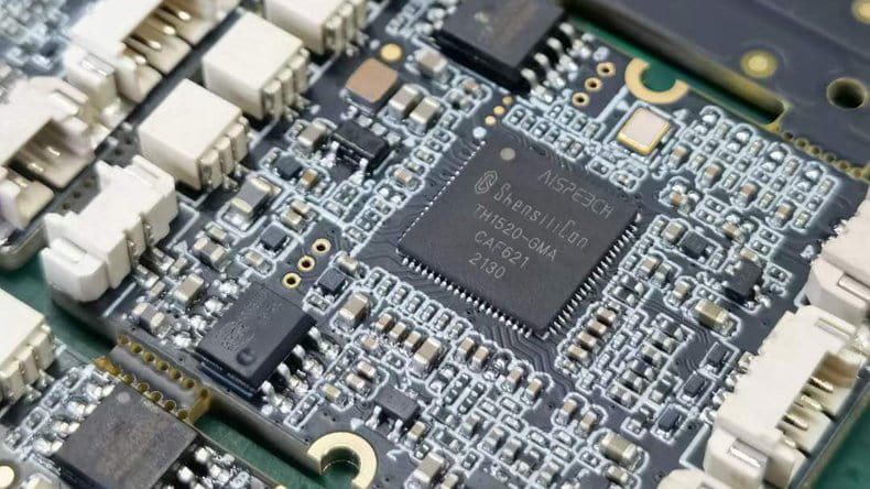
The drawing should carry pocket location, depth, tolerance, wall angle and corner radius, because a stencil supplier will otherwise machine to a house default. Note the design revision beside the pocket, since an aperture change nearby can move the pocket edge closer to the neighbouring pads. The numbering rules used for panelization are a sound basis for that drawing. The numbering rules used for <a href=\
First article should confirm three things: pocket depth on the finished foil, printed deposit height in both zones, and solder joint quality after reflow. The stencil, the printing setup and the profile each contribute, and skipped deposits on mixed boards often trace back to a step that was never verified.
FAQ
When is a cavity stencil better than a second print? When the volume difference is modest and the panel area that needs less paste is small. A pocket adds one tooling cost to an existing foil, while a second print adds a machine pass, a second alignment and another chance to shift the deposit. Above roughly half the base thickness, the second print wins.
How deep can a pocket be before printing suffers? Depth on its own matters less than depth against foil thickness. A step that removes more than half the foil leaves a thin lip that flexes under the blade and wears quickly. Past that point, reduce the base foil and print twice, or use a stepped foil built from two bonded layers.
Does a cavity stencil change the reflow profile? It changes the paste mass in the pocket zone, and less paste means the joint reaches temperature faster. The difference is usually small, but the profile should be rechecked with thermocouples on a full thickness pad and on a pocket pad before the order is released.