Ceramic-Filled Laminates for Stable Microwave Performance
Microwave circuits are sensitive to their substrate in a way that digital circuits are not. A filter, a coupler or a resonant antenna has a response that depends directly on the dielectric constant, and a change of a few percent shifts the centre frequency by a comparable amount. That is why a class of laminates exists whose defining feature is not the lowest possible loss but a tightly specified and stable dielectric constant.
This article explains why the specification of a microwave substrate matters, how ceramic-filled materials achieve it, and when the premium over a general-purpose low-loss laminate is justified.
Why a Defined Dielectric Constant Matters
Every dimension in a microwave design is derived from the dielectric constant. A quarter-wave stub, a coupled-line coupler and a patch antenna all scale with it, so an error in the assumed value produces a structure that resonates at the wrong frequency. Where the design is narrowband, that error can be larger than the bandwidth of the device.
The tolerance is therefore a design input rather than a manufacturing detail. A material specified as 10.2 plus or minus 0.25 gives a frequency tolerance about half that of one specified as 10.2 plus or minus 0.5, and in a filter design the difference is visible in the passband edges. Buying a tighter tolerance is cheaper than adding tuning elements to every unit.
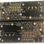
<img src="https://www.gopcba.com/wp-content/uploads/2026/09/225-1.jpg" alt="Ceramic-filled laminate used in a microwave circuit” />
Ceramic-Filled Versus PTFE Materials
Two families dominate the high-performance end. PTFE-based materials with a glass or ceramic filler offer the lowest loss tangent, but they are soft, they move during processing, and their dielectric constant is harder to hold. Ceramic-filled hydrocarbon materials are stiffer and more dimensionally stable, and their dielectric constant can be specified to a tighter tolerance, at a slightly higher loss.
The choice follows from the requirement. A low-loss feed network in a receiver benefits from the PTFE family. A filter or a coupler that has to be manufactured repeatably benefits from the stability of the ceramic-filled family. Where both matter, the design usually ends up with a hybrid stack or with the ceramic-filled material throughout, because the loss difference is often smaller than the tolerance difference in practice.
Dielectric Constant Across Frequency and Temperature
A material whose dielectric constant varies with frequency is difficult to design with, because the simulation has to be run at each frequency of interest with the correct value. Materials in this class are characterised over a wide range and their variation with frequency is specified, which allows the designer to use the right figure at each band.
Temperature behaviour is specified similarly. The coefficient is quoted in parts per million per degree, and a low figure means the centre frequency shifts very little across the operating range. For a base station filter that has to work from -40 to +85 degrees, that coefficient is one of the most important parameters on the datasheet.
Loss Tangent and Where It Comes From
Loss in a laminate has two parts: the dielectric loss, which is proportional to the loss tangent and to frequency, and the conductor loss, which depends on the copper surface and the geometry. In this class of materials the dielectric loss is low enough that conductor loss becomes the larger term at high frequency, which changes where the design effort should go.
That is a useful shift. If the dielectric is no longer the limit, effort spent on smoother copper, wider traces or a shorter path returns more than effort spent on a lower-loss material. The microstrip and stripline routing rules cover the geometry choices that reduce conductor loss, and the microwave fabrication notes describe how the process affects the result.
Dimensional Stability and Processing
A material that changes dimensions during processing cannot hold a tight tolerance on the finished board, whatever its dielectric constant specification says. Dimensional stability is quoted as a percentage change through the process, and a low figure means the artwork can be scaled once rather than adjusted after the first article.
Processing behaviour differs from FR-4 as well. These materials often need a different drilling recipe, a longer lamination cycle and a specific surface preparation before plating. A fabricator who does not build them routinely will produce boards that meet the drawing and miss the electrical performance, which is why the supplier’s process history matters as much as the material specification.
Transmission Line Geometry on These Materials
A higher dielectric constant permits a narrower trace for the same impedance, which is useful when several lines have to fit into a small area. The trade-off is that a narrow trace on a thin substrate concentrates the field and raises the conductor loss, so the geometry should be chosen against the loss budget rather than against the available space alone.
Coupled structures are more sensitive still, because their coupling depends on the gap and the dielectric constant together. Where a coupled-line coupler is designed on a substrate with a tight dielectric constant tolerance, the coupling value can be held without trimming. The high-frequency routing guidance covers how these lines should be arranged relative to each other and to the ground.
Thermal Behaviour
Thermal conductivity in these laminates is higher than FR-4, which helps with the small amount of heat that a passive microwave circuit generates and, more importantly, reduces the temperature gradient across the board. A uniform temperature matters because the dielectric constant moves with temperature, and a gradient across a filter produces a response that cannot be compensated with a single coefficient.
The coefficient of thermal expansion is also relevant where the board is bonded to a metal housing or carries a large connector. A mismatch between the laminate and the metal produces stress at the fixings, and over thermal cycling that stress can crack a solder joint or delaminate the board at the mounting points.
When the Premium Is Justified
These materials cost several times more than FR-4, and the premium should be justified by a requirement rather than by a preference. The clearest cases are narrowband circuits where the centre frequency has to be held, arrays where every element has to match, and designs that operate across a wide temperature range without retuning.
Where the circuit is broadband, or where the tolerance on the response is loose, a general-purpose low-loss laminate will often be adequate at lower cost. The decision is best made by propagating the material tolerance through the circuit model and reading the resulting spread in the response, rather than by comparing datasheet figures in isolation.
FAQ
Does a tighter dielectric constant tolerance remove the need for tuning? It reduces the need but does not remove it. Some designs still include a tuning element for the production spread, but the range over which it has to work becomes much narrower, which simplifies the tuning operation.
Can these materials be mixed with FR-4 in one stack? They can, and hybrid stacks are common where only some layers carry the microwave circuit. The two materials have different expansion rates and process requirements, so the transition has to be planned and the impedance calculation has to use the correct permittivity on each layer.
Is the loss always lower than a general-purpose laminate? Not always. Some materials in this class trade a little loss for better stability, and a general-purpose low-loss laminate may have a lower loss tangent. The comparison should be made at the frequency and the temperature the design actually uses.