Ceramic Substrate PCB Advantages for Thermal and RF Designs
Ceramic substrates appear in designs where the thermal load, the operating frequency or the environment rules out ordinary laminate. They cost more per square centimeter and they cannot be processed like a conventional board, but they solve problems that no amount of copper can fix. Knowing where a ceramic substrate PCB earns its cost is the key to choosing it for the right reasons.
What Makes Ceramic Substrates Different
A ceramic substrate is an insulating plate, usually alumina, aluminum nitride or a low temperature co-fired ceramic, with conductors formed on its surface by thick film printing or by co-firing a metal paste. The result is a rigid, dimensionally stable base with excellent thermal conductivity and very low dielectric loss.
Alumina dominates because it is inexpensive and well understood, with thermal conductivity several times that of FR-4. Aluminum nitride offers far higher conductivity and is chosen for power devices where the junction temperature is the limiting factor. Low temperature co-fired ceramics allow multiple layers with buried passives, which is useful at radio frequencies where discrete components are undesirable.
Thermal Conductivity and Power Density
The reason most designs move to ceramic is heat. A power device mounted on a ceramic substrate conducts into the base directly, without the dielectric barrier that limits a metal core board, and the base spreads the heat laterally before it reaches the heatsink. This allows much higher power density in a small footprint.
The thermal path should be designed as a chain and evaluated end to end: junction to case, case to the metallization, metallization to the ceramic, ceramic to the mounting surface. The lowest conductivity in that chain sets the performance, so improving the ceramic while leaving a poor interface under it produces very little gain.
Coefficient of Thermal Expansion and Reliability
Ceramic has a coefficient of thermal expansion much lower than most metals and laminates. That is an advantage when the device being mounted is also ceramic or silicon, because the joint experiences less strain over temperature. It becomes a problem when a large metal heatsink is attached rigidly, since the mismatch is then transferred into the substrate and can crack it.
Managing the mismatch is a mechanical design task. Use compliant mounting, allow the substrate to move, or select a base material whose expansion is closer to the mating part. Thermal cycling tests at the extremes of the specified range reveal whether the joint survives, and they should be part of the qualification rather than a final formality.
High Frequency Loss and Stability
At radio frequencies, ceramic keeps high frequency loss low and provides a stable dielectric constant that changes very little with temperature. Thick film conductors can be printed with tight tolerances, and the geometry is reproducible from lot to lot, which is what makes ceramic attractive for filters, couplers and matching networks. Circuit functions that would need tuning on a laminate can be printed once and repeated.
The dielectric constant of alumina, around 9 to 10, is high compared with laminate, which means narrow traces and compact structures. That is useful for shrinking a filter, and it also means the design is more sensitive to dimensional variation, so the printing tolerance must be considered in the design margins.

Thick Film Metallization and Assembly
Thick film metallization is produced by screen printing a metal paste and firing it at high temperature. The process supports fine conductor patterns, printed resistors and multilayer structures, and it tolerates high operating temperatures that would degrade a polymer board. Components are attached with high temperature solder or with conductive adhesive, and wire bonding is common for bare die.
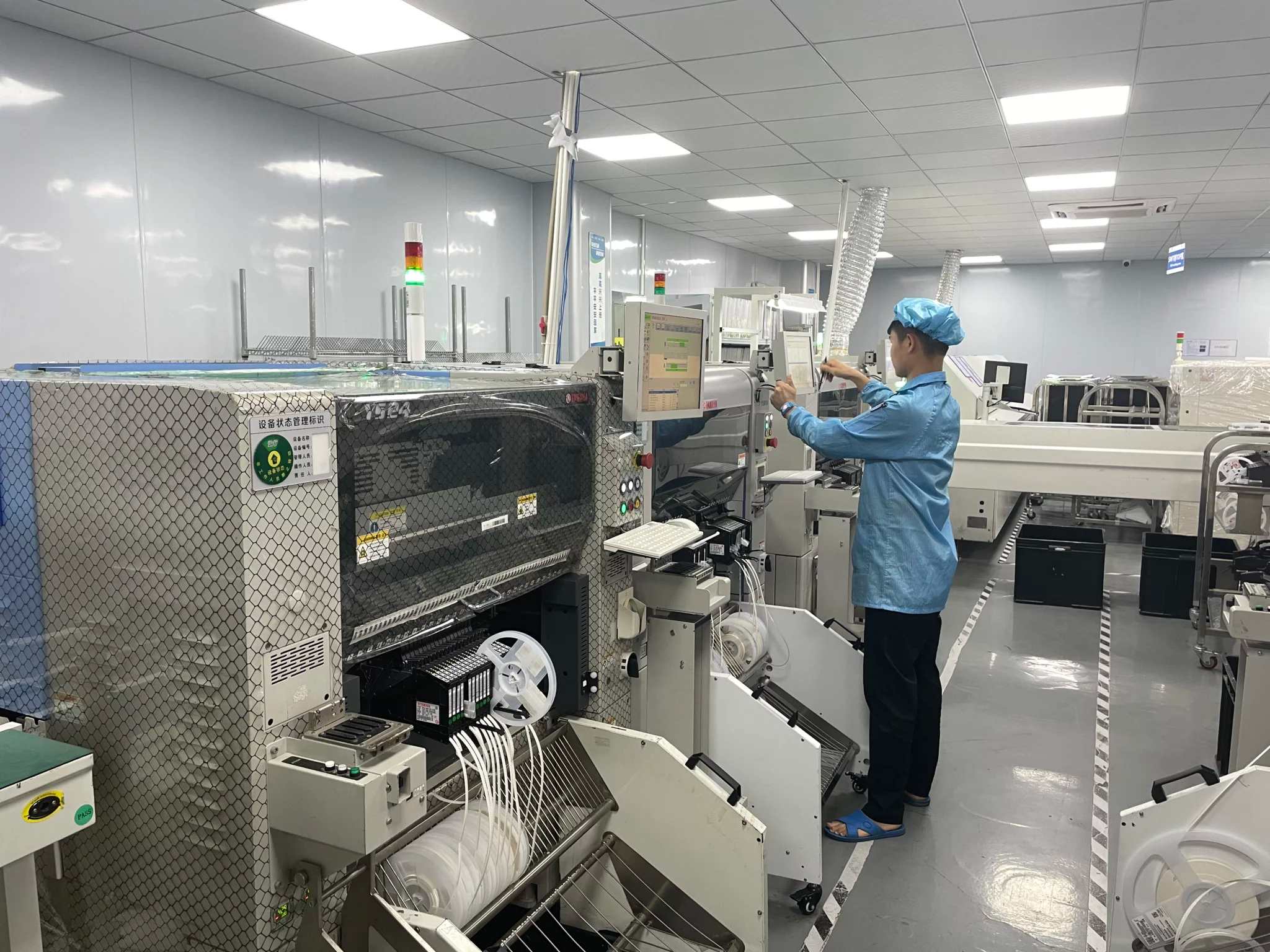
Assembly on ceramic requires different process settings from a laminate board. The substrate is rigid and brittle, so it must be supported during singulation and handled with care; the solder alloys used are often higher melting point than standard assembly paste; and cleaning must not attack the metallization. Select an assembler who works with ceramic routinely, because the process window is narrower than on FR-4.
Where Ceramic Substrates Fit
Typical applications include power modules, radio frequency front ends, high temperature sensors and automotive electronics mounted close to the heat source. In each case, the driver is one of three constraints: power density, frequency or temperature. Where none of those constraints is severe, a laminate or metal core board will be cheaper and easier to build.
The decision should compare total cost rather than substrate cost. Ceramic may eliminate a heatsink, remove a cooling fan, or allow a smaller enclosure, and those savings often exceed the material premium. gopcb works with ceramic and metal core constructions and can review the thermal path and the assembly process before the design is committed to a specific substrate.
Design Rules for Ceramic Layout
Conductor geometry is limited by the printing process rather than by etching. Minimum line width and spacing are larger than on a fine pitch laminate board, so the layout must be planned with that limit from the start instead of being compressed later. Current carrying capacity per unit width is higher because heat leaves the conductor quickly, but the total permissible current still depends on the allowed temperature rise and should be checked with trace width and current calculation adjusted for the substrate.
Printed resistors are one of the advantages of the technology, because they can be placed and trimmed to value and they eliminate a component and two joints. Their tolerance and temperature coefficient are poorer than a discrete resistor, so they suit functions where a few percent is acceptable. Where precision matters, keep the discrete component and use the ceramic for its thermal properties.
Substrate Selection Checklist
Work through the constraints in order. First the maximum junction temperature and the power to be dissipated, which decide whether alumina is enough or aluminum nitride is required. Then the frequency and loss budget, which decide the material and the metallization. Finally the environment, including the number of thermal cycles and any chemical exposure, which decides the finish and the assembly process.
Compare the result with a metal core or thick copper laminate alternative, following aluminum versus copper core PCB comparisons and high precision PCB material selection practice, because those options are often adequate at a fraction of the price. Reserve ceramic for the cases where the numbers genuinely require it.
One practical check closes the evaluation: build a small test coupon with the intended metallization and measure the actual thermal resistance and the loss at the operating frequency. Coupon data removes the uncertainty in the supplier figures and provides a reference for later lots, which is the same discipline that makes impedance control possible on laminate boards.
FAQ
Is ceramic better than a metal core board for thermal management? For very high power density, yes, because the dielectric barrier is thinner and the base conducts better. For moderate power with a large area, a metal core board is usually cheaper and adequate.
Can ceramic substrates carry multilayer circuits? Co-fired ceramics support many layers with buried passives, while thick film on alumina is usually single or double sided. The choice depends on the frequency and the component count rather than on thermal needs alone.
Why does ceramic crack in the field? Almost always because of a mechanical or expansion mismatch with a rigidly attached part, or because the substrate was stressed during singulation. Both causes are visible in a cross section of the failed assembly.