Panel Mounting and Soldering of Coaxial Connectors
A coaxial connector that passes through an enclosure wall carries two joints at once. Inside the box it is soldered to the board, and at the wall it is mechanically fastened to the panel. Both have to work, and the electrical performance of the assembly depends on them as much as on the connector itself. A perfectly chosen connector mounted badly will show a return loss far worse than its datasheet suggests, and no amount of cable assembly work downstream will recover it.
The mechanical and the electrical requirements are also coupled. Torque that is applied to the panel nut is transmitted through the connector body to the board joint, so an over tightened nut can crack a solder fillet or lift a pad. Designing the mounting so that the two loads are separated is the first step towards a reliable assembly.
Ground Continuity Is the Dominant Requirement
The shield of a coaxial connector has to be connected to the reference plane of the board with the lowest possible inductance, and the connection has to be continuous around the full circumference. Current on the inside of the shield returns along the transmission line, and current on the outside is the common mode current that causes emission. A shield that is grounded at a single point or through a narrow trace lets the outside current develop a voltage, and that voltage drives the cable as an antenna.
The practical consequence is that the connector footprint should have a ground pad that surrounds the signal pad and is connected to the plane with vias placed immediately beside it, ideally around the whole perimeter. Two vias on one side of the connector is a common layout and a poor one, because the inductance of that path is high enough to matter at the frequencies where the connector is used. Four or more vias distributed around the pad give a much lower impedance.
Panel Mounting and Torque Control
The panel joint is made with a nut, a bulkhead flange or a compression fitting, and each has a specified torque. Exceeding it deforms the connector body or crushes the panel material, while applying too little leaves the joint loose and lets it rotate as the mating connector is tightened. The torque specification comes from the connector manufacturer and should be transferred onto the assembly drawing, together with the wrench size and the sequence if more than one nut is involved.
Reaction force is the hidden problem. Tightening a nut on the outside of a panel applies a torque to the whole connector, and if the board connection is the only thing resisting that rotation, the joint absorbs the load. A common solution is to hold the connector body with a second wrench while the nut is tightened, or to use a connector with flats that can be held in a fixture. Where the connector is mounted before the board is fitted, the assembly sequence itself provides the restraint.
Soldering the Board Connection
The board joint is made to a pad that is part of the transmission line structure, and its geometry determines the impedance at that point. A solder fillet that flows across the gap between the signal pad and the surrounding ground is a short circuit; a joint with insufficient solder increases the inductance. The pad should therefore be designed so that the solder has a defined place to go, with a ground clearance that the assembly process can hold.
Thermal mass influences the joint as well. A connector body with a large metal mass conducts heat away from the joint, so the soldering process has to deliver more energy or preheat the assembly. For a hand soldered joint this means a larger iron tip and a longer dwell, both of which stress the board. Where a reflow process is used, the connector has to be able to withstand the profile, and its plastic parts must be rated for the peak temperature.
Assembly Sequence and Its Consequences
The order in which the parts are assembled determines which joint carries which load. Mounting the connector to the panel first and then soldering it to the board is often the better sequence, because the panel fixing is completed before the electrical joint exists and therefore cannot damage it. The opposite order requires the board to be held accurately while the panel nut is tightened, which is difficult and rarely done consistently.
Where the connector is fitted to the board first, the assembly drawing should show the part of the connector that may be gripped by a fixture and the torque that the board joint can tolerate. Supplying a mating connector as a holding tool is a practical trick: the mating part provides a grip that does not load the solder joint at all. It is a small instruction that prevents a recurring defect.
Verification
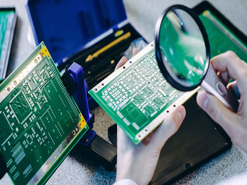
Verification combines a mechanical and an electrical check. Mechanically, the connector should be inspected after assembly for rotation, for a lifted pad or for a cracked fillet, and a torque test on a sample should confirm that the specified value does not damage the joint. Electrically, a return loss or a time domain measurement through the connector shows whether the launch and the ground connection are correct, and comparing the result with a measurement of a bare board connector launch isolates the contribution of the assembly.
Repeatability is the reason to measure rather than to inspect. A launch that is visually acceptable can still have a poor return loss because the ground vias are too far from the pad or because the solder has wicked into the gap. Measuring a sample from each build, and recording the result with the assembly, is what turns a connector mounting detail into a controlled part of the design. The same approach to maintaining a defined impedance discontinuity applies to any connector on a controlled impedance board.
Routing the Cable Inside the Enclosure
Once the connector is mounted, the cable that mates with it runs inside or outside the enclosure, and its route affects the performance of the whole assembly. A cable that runs parallel to a slot or a seam for a long distance couples to it, and the resulting common mode current appears as emission even though the connector itself is well grounded. Keeping the first few centimetres of the cable away from structure, and routing it away from the board rather than alongside it, reduces that coupling considerably.
Strain relief is the mechanical counterpart. The cable should be clamped so that any pull is taken by the enclosure rather than by the connector and its solder joints. A clamp placed close to the connector also fixes the cable geometry, which keeps the launch impedance consistent from unit to unit. Where the cable must cross a hinge or a moving part, the design should allow a service loop so that the movement is absorbed by the loop rather than by the connector.
Related reading: our fabrication notes, board quality and design release notes cover the same ground.
FAQ
How many ground vias does a coaxial launch need? Enough that the inductance of the ground path is negligible at the highest frequency of interest. Four or more vias distributed around the pad is a reasonable starting point for a connector used above a few gigahertz.
Can a panel nut be tightened after soldering? It can, but the joint then carries the torque. Holding the connector body with a second wrench, or using the mating connector as a grip, avoids the risk.
Why does a connector measure worse than its datasheet? Almost always because of the launch and the ground connection rather than the connector. Measuring a bare launch and a fully assembled one separates the two.