Component Cracking in Reflow: Thermal Shock and Moisture
A cracked component is a failure that is often invisible at the end of the assembly line and certain to appear in the field. The crack may run through a ceramic body, through the encapsulation of a plastic package or through the dielectric layers of a multilayer capacitor. Component cracking during reflow is produced by three different mechanisms, and separating them matters because the remedies are different and the wrong one wastes time without improving the yield.
How Components Crack
The first mechanism is thermal shock, a rapid change in temperature that sets up a stress gradient across the body. The second is internal pressure from moisture that turns to steam inside the package. The third is mechanical bending, either during handling or when the board flexes and the component is forced to follow.
Each leaves a characteristic mark. A thermal shock crack usually runs across the body from a termination. A moisture-driven crack starts internally near the die pad and often produces a bulge on the outside. A flexural crack runs through the body at right angles to the board.
Thermal Shock and Ramp Rate
Ceramic bodies are brittle and have a low tolerance for a rapid temperature change. The stress is proportional to the temperature difference across the body and to the difference in expansion coefficient between the ceramic and its termination, so a fast ramp and a large thermal mass nearby both increase the risk.
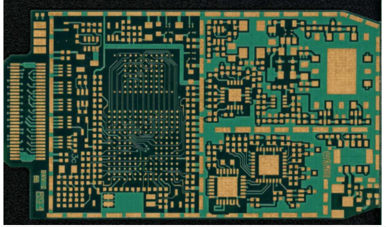
The practical control is the ramp rate in the preheat stages of the profile. Most specifications limit the rise to between 2 and 4 C per second, and the limit applies to the component surface rather than to the oven air. Where the assembly has a large thermal mass, the difference between the two can be significant, and the profile should be verified with a thermocouple attached to a representative component.
Moisture and Popcorning
Plastic packages absorb moisture from the air. When the package is heated rapidly, the moisture inside turns to steam, the pressure rises and the package can crack or delaminate from the inside. The effect is called popcorning because of the sound it makes when it happens.
The industry manages it with moisture sensitivity levels and floor life limits. A component stored in a moisture barrier bag has a defined floor life after the bag is opened, and once that is exceeded the component must be dried before reflow. Ignoring the floor life is the single most common cause of popcorning in a shop that otherwise controls its profile well.
Flexural Cracks From Handling and Singulation
A flexural crack comes from board bending after the components are attached. The component is rigid, the board is not, and any bending forces the component to follow the board until the ceramic gives way. The crack is usually a clean break through the body, often with no visible damage to the solder joints.
The damage can occur after assembly as well as during it. Separating a panel by hand, over-tightening a mounting screw, or pressing on a board that is supported only at its corners will all produce the same result. The crack may appear immediately or it may be latent and grow with thermal cycling, which is why a board that passes functional test is not evidence that the components survived the process.
Board Support and Depaneling Effects
Support during depaneling is the most common place to lose components. A router or a scoring operation applies a load at the panel edge, and if the array is not supported underneath the parts nearest the cut, the board bends and the components crack. A support plate positioned under every part, not only under the cut line, is the standard remedy.
Hand separation of breakaway tabs is worse, because the load is uncontrolled. Where tabs are used, they should be designed so that the force needed to break them is low, and the panel should be supported on both sides of the break. The same consideration applies to placement and alignment work carried out after assembly.
Profile Settings That Reduce Risk
Three settings reduce the risk. A slower ramp limits the thermal gradient across the body. A soak that brings the whole assembly to a uniform temperature before the peak reduces the gradient further and allows absorbed moisture to leave plastic parts gradually. A controlled cooling rate, usually below 4 C per second, prevents the reverse gradient as the assembly leaves the zone.
The peak temperature also matters, but the exposure time above liquidus contributes the larger part of the thermal dose. Where a profile is aggressive to gain throughput, the components at the edges of the panel and those with the largest thermal mass are the ones that fail first, because they experience the largest gradient across the body.
Detection and Inspection
Optical inspection finds surface cracks on a ceramic body only if the crack is visible and the inspection angle is right. Many flexural cracks run on the underside or through a termination and are invisible. Acoustic microscopy can find internal delamination in a plastic package, and thermal shock testing followed by electrical measurement will reveal latent damage.

The most practical tool is a section. A microsection through a suspect component shows the crack path and its origin, which distinguishes a thermal crack from a mechanical one. Sectioning a known-good part alongside the suspect is useful, because the crack path can otherwise be ambiguous.
Storage and Baking Rules
Moisture control starts at goods-in. Components in moisture barrier bags should be stored sealed, the bag should be opened only when the parts are needed, and the floor life should be recorded from the moment of opening. Parts that exceed the floor life are dried according to the supplier’s recommendation before use.
Baking carries its own risks. It removes moisture, but it also ages the terminations and may affect solderability, so the temperature and duration should come from the component supplier rather than from a general rule. Repeating a bake more than the recommended number of times is usually treated as a rejection.
Records and Supplier Interaction
The record should carry the component part number, the moisture sensitivity level, the date the bag was opened, the accumulated floor time, the profile used and any baking applied. That record is what separates a process problem from a supplier problem when a crack is found.
Where cracks appear on one component type and not others under the same profile, the difference is usually in the body material or the termination design, and the supplier should be asked for the thermal shock specification that applies. The comparison between the component rating and the measured profile is the evidence that resolves the question.
FAQ
What causes a crack in a ceramic capacitor during reflow? Thermal shock from a fast ramp, internal steam pressure from absorbed moisture, or mechanical bending of the board after soldering. The crack path in a section usually identifies which one applies.
What ramp rate is safe for reflow? Around 2 to 4 C per second is common, measured at the component rather than in the oven air. Larger thermal mass makes the difference between the two significant.
Can a cracked component still pass electrical test? Often yes. A flexural crack may not break the connection immediately, so the failure appears later as a leakage or an open circuit after thermal cycling.