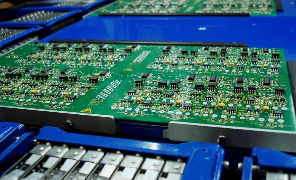
Component Placement Offset: Fiducial Recognition and Vision Alignment
A placement offset is the difference between where a component sits and where the pad pattern says it should sit. Small offsets are absorbed by the self-aligning action of the solder during reflow; larger ones leave joints with unequal fillets, reduce the stand-off on a ball grid array, or push a lead outside the pad on a fine-pitch part. Controlling placement offset is therefore a matter of finding where the error enters the machine and removing it, rather than of tightening a single number in the program.
Where Placement Offset Comes From
Four sources are worth separating. The board may not be where the machine believes it is, the component may not be where the feeder believes it is, the head may not be where its own axis says it is, and the nozzle may not have picked the part on centre. Each produces a characteristic pattern, and the pattern is what identifies the cause.
A uniform offset in one direction across the whole board points to the board or to the fiducial. An offset that grows along one row points to the axis calibration or to temperature drift. An offset that varies randomly from part to part points to pick-up or to the feeder.
Fiducial Recognition and Panel Datums
Fiducials define where the board is. They are usually copper marks with clear space around them, placed diagonally opposite each other so that the machine can work out translation, rotation and in some cases scale. A fiducial that is partly covered by a component, by a tooling hole or by a panel feature cannot be found reliably, and the machine then interpolates from one mark.
Panel datums are the second layer. The position of the board within the array depends on the panel outline and on the breakaway tabs, and the position of the array within the machine depends on the conveyor and on the tooling pins. Errors that appear only on panels from one supplier usually point to the datum rather than to the machine.
Vision Alignment on the Machine
Vision alignment compares the fiducial image with the stored template and computes the correction. The camera resolution, the field of view and the lighting together determine how accurately that correction is made. Small marks need a small field of view to resolve, but a small field of view can lose the mark if the offset is large, so the machine searches a wider area first and then refines.
Lighting is frequently the limiting factor. Fiducials under solder mask need a diffuse light and a colour that separates mask from copper; bare copper marks require a different setting altogether. A machine that is calibrated for one finish and then run on another gives the same result as a miscalibrated machine, and the fault is easy to misread.
Machine Accuracy and Repeatability
Pick and place accuracy is not one number. Accuracy is how close the head gets to the target; repeatability is how close successive attempts are to each other. A machine with poor accuracy but good repeatability can be corrected by calibration offsets. A machine with poor repeatability cannot, because the error moves from part to part and no fixed offset will remove it.
Repeatability is normally verified with a glass plate or a calibration board measured at several points over the working area. It should be checked after any crash, after a head or nozzle replacement, and at a defined interval. Where the machine has multiple heads, each head should be verified separately, because a single head that is out of specification affects only the parts it places.
Nozzle, Feeder and Component Presentation
The nozzle picks from the centre of the part only if the part is presented at the centre of the pick position. Feeder pitch error, tape pocket size, a worn sprocket or a damaged cover tape all move the part sideways, and the nozzle then picks it off centre. A part picked off centre is placed off centre by the same amount, regardless of what the vision system measures afterwards.
Nozzle condition matters as much. A blocked nozzle, a worn tip or a nozzle that is too large for the part allows the component to move during the transfer. Where the machine measures the component after pick-up, the measurement corrects the position but not a part that is still sliding on the nozzle.
Placement Tolerance Versus Pad Geometry
Placement tolerance is the maximum offset allowed by the design. It is set from the pad width, the lead or ball dimension and the minimum acceptable joint, and it is normally a fraction of the available margin rather than the whole of it. Reflow consumes part of that margin, so a tolerance that uses all of it leaves nothing for the soldering process.
For a chip component, a common rule is that the offset should not exceed a quarter of the terminal width; for a fine-pitch leaded part, a tenth of the pitch; and for a ball grid array, a small fraction of the ball diameter. These are starting points, and the actual limit is the offset at which the joint still meets its acceptance criteria.
Self-Alignment During Reflow
Molten solder pulls a component towards the centre of its pad through surface tension, which is why the process tolerates offsets that would otherwise be unacceptable. The force is strongest while the solder is liquid, so a longer time above liquidus gives more correction, and a uniform paste deposit gives a symmetric force.

The same force can work against the process. An asymmetric deposit pulls the part to one side, and the result is component skew even though the placement was correct. Where skew appears on one component type but not on others, the paste deposit and the pad geometry are the variables to examine before the placement program.
Measuring Offset and Correcting the Program
Offset is measured after reflow with an automated optical inspection system that reports the displacement of each part from its pad reference. Trending the mean offset by component type and by position on the board separates a global error from a local one, and the mean is more useful than the individual readings.
Correction follows the pattern. A global mean is corrected with a machine offset or by re-teaching the fiducials. A mean that differs by feeder or by head is corrected at that feeder or head. A mean that differs by board position and follows the panel through the line is corrected in the stencil or in the pad design, not in the placement program.
First Article and In-Process Checks
The first article should include a measurement of placement offset for each package family, taken before reflow and again after, so that the self-alignment contribution is visible. The pair of numbers tells the process engineer how much margin the reflow is actually providing.
In production the checks are the fiducial recognition rate, the nozzle and feeder maintenance counters, and the offset trend from inspection. A rise in the number of parts that the machine fails to recognise is an early warning of a fiducial problem, and it usually appears before the offset itself moves out of tolerance.
FAQ
How much placement offset is acceptable? It depends on the package. A working rule is a quarter of the terminal width for chip parts, a tenth of the pitch for fine-pitch leads and a small fraction of the ball diameter for a ball grid array, confirmed against the joint acceptance criteria.
Can reflow correct a placement error? It can correct small offsets through self-alignment while the solder is molten, but the force depends on a symmetric paste deposit. A large offset or an unbalanced deposit will not be corrected and may be made worse.
Why does offset appear only on one head of a machine? Because each head has its own nozzle, its own axis and its own calibration. Verifying heads separately with a glass plate or calibration board isolates the fault to one head instead of the whole machine.