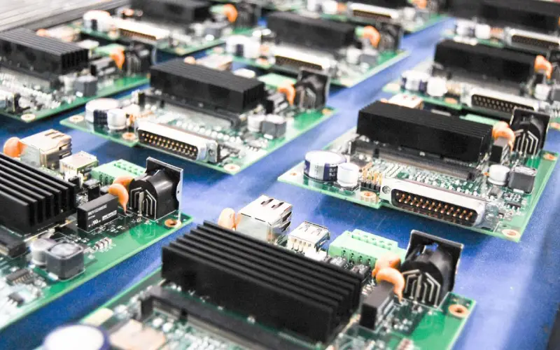
Component Polarity And Orientation Verification
A component that is placed in the right position but rotated by a hundred and eighty degrees passes every positional check in the machine. It sits flat, its terminals land on the pads, and the paste wets on both ends, so the placement system reports success and the board moves on. The error is only discovered by an inspection that reads the part marking, by an electrical test that detects a reversed junction, or by a customer. Polarity is therefore a separate verification problem from position.
This article explains why orientation errors happen, what has to be verified, which design and process measures prevent them, and how they are detected.
Why Orientation Errors Happen
The most common cause is the tape. A component sits in its pocket in a defined relationship to the sprocket holes, and a reel that is wound the other way presents every part rotated, as described under placement order and pad positioning. The second is the footprint library: a library part that was drawn with pin one in a different corner from the physical package, or a package variant whose pin one moved between the drawing and the part that is now being bought.
The third cause is human. A manual placement, a rework operation, or a hand loaded part is placed by someone reading a marking on a small package with poor contrast, and the likelihood of an error rises with the age of the board revision and with the number of similar parts on it. The fourth is a design change: a footprint that was rotated during a layout revision, with the silkscreen updated and the placement program not, or the reverse.
What Has To Be Verified
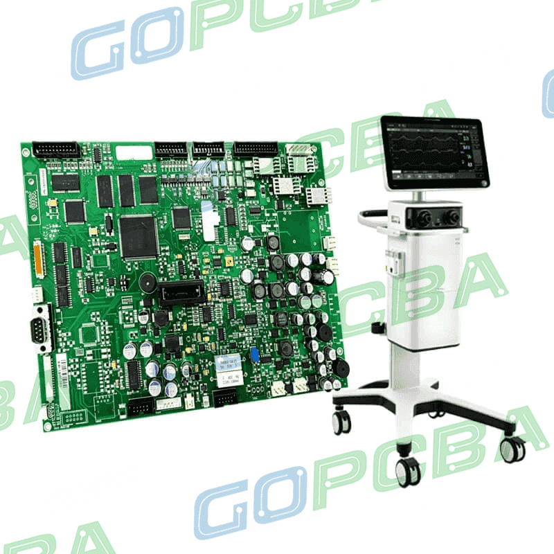
The parts that matter are the ones whose function depends on orientation. A diode has a cathode band, an electrolytic capacitor has a polarity stripe and, on some packages, a marked terminal, a tantalum capacitor has a polarity bar, a light emitting diode has a flat on its body or a shorter lead, and an integrated circuit has a pin one marker that is often a dot, a chamfer, or a bevelled corner. A transistor has a pinout that changes between the SOT packages, and a connector has a pin one and a mating orientation that determines whether the cable enters from the correct side.
The less obvious cases are worth listing as well. An inductor or a transformer with a polarity dot, a crystal with a marked pin, a diode array with a common terminal, and a polarized connector that can be inserted in one orientation only. The verification is easiest when the marking is visible after placement, which is a design property rather than a process one.
Design Measures That Prevent Errors
A consistent footprint library removes one class of error, and a convention that pin one is always drawn at the same position in the library removes another, because a reviewer can then check the orientation at a glance. The pad shape is a strong cue: a square pad for pin one with the rest round, or a chamfered pad on the cathode side of a diode, is visible on the bare board and in the placement image.
The silkscreen is the third measure. A pin one marker drawn outside the package body, a cathode bar beside the diode, and a polarity symbol for a capacitor are all visible to an operator and to a camera, and they are also visible after the part has been placed if they are drawn beside rather than under the body. Where space does not allow a symbol, a mask opening in the shape of the polarity mark serves the same purpose.
Process Measures
The first article inspection is where the orientation of every polarized part is confirmed against the assembly drawing, and it is the least expensive place to find an error. The inspection is performed with the marking visible, which means before the parts are covered by a shield, a connector, or a coating, and the record of that inspection belongs with the traveler.
The automated optical inspection program is the second measure, and it works only if it checks the marking rather than the position. A program that verifies the presence of a part and its offset does not detect a rotation of a two terminal component, because both positions look the same to a shape based algorithm. A polar check, which reads the marking or the polarity feature, is a separate algorithm and has to be programmed and verified deliberately for each footprint.
Detection And Escape Analysis
Electrical test catches some orientation errors and misses others. In circuit test can detect a reversed diode through the forward voltage, and it can detect a reversed electrolytic capacitor only if the test applies a polarity sensitive measurement. A functional test is the final barrier and it catches the errors that change behaviour, but a reversed decoupling capacitor or a reversed inductor may pass both tests and fail later.
When an orientation error is found, the escape analysis is the useful work. The question is not who placed the part but which control allowed the error to pass: a reel that was loaded inverted, a library part that never matched the package, a polar check that was never programmed, or a first article that was signed without the marking visible. Each of those is a correctable control, and the correction is what prevents the second occurrence. The wider acceptance framework is described under PCB design quality characteristics, and the pad geometry that carries the polarity cue under pad design standards.
Process Control and Verification
On a design of this kind, polarity is the item that decides how the rest of the board is arranged. A stack-up that is drawn rather than described removes most of the ambiguity from a quotation, and it lets the fabricator price the board against the dielectric and copper weights that will actually be used. Where the requirement is not written down, the shop supplies its own default, and the default is chosen for the process rather than for the design.
The measurements that matter are the repeatable ones: conductor width and spacing, annular ring, finished hole size, plating thickness and surface finish are all verifiable on a coupon that travels with the panel.
Process Control and Verification
On a design of this kind, polarity is the item that decides how the rest of the board is arranged. A stack-up that is drawn rather than described removes most of the ambiguity from a quotation, and it lets the fabricator price the board against the dielectric and copper weights that will actually be used. Where the requirement is not written down, the shop supplies its own default, and the default is chosen for the process rather than for the design.
FAQ
Why does a positional check not detect a rotation? Because both orientations present the same outline to the camera. Only a check that reads the marking or a polarity feature distinguishes them.
Can electrical test catch every orientation error? No. It catches reversed junctions and some polarized parts, but a reversed non polarized component usually passes and appears as a functional or a reliability problem later.
What is the cheapest control? A first article inspection performed with every marking visible, supported by a footprint library convention and a pin one marker on the silkscreen that can be read after placement.