Conformal Coating Rework Practice for PCB Assemblies
A conformal coating protects a circuit from moisture, contamination and mechanical damage, and it also makes any subsequent repair more difficult. The coating has to be removed locally before the joint can be reworked, and then the protection has to be restored so that the repaired area is as reliable as the rest of the board. This article covers the order of operations, the removal methods and their risks, and the rules that keep rework from becoming the weak point of an otherwise well protected assembly.
Why Coated Boards Have to Be Reworked
A board is reworked after coating for the same reasons it is reworked before: a failed test, a component change, a customer return or a late engineering change. The difference is that the coating now has to be dealt with, and that changes the difficulty of every step.
The decision to rework should be made deliberately. A coated assembly has already passed a process that was designed to protect it, and rework removes that protection from a local area. Where the defect is marginal, replacing the assembly is sometimes the cheaper and the safer answer. The cost of the rework is not only the labour; it is the risk that the repaired area becomes the least reliable part of the product.
The Order of Operations
The sequence is to identify the area, remove the coating, perform the repair, clean the area, restore the masking, recoat and cure, and then inspect. Skipping the cleaning step or the cure step is the most common way a repair becomes a reliability problem rather than a repair.
The area to be opened should be defined before any tool touches the board. Removing more coating than necessary creates a larger area to restore, and removing too little leaves coating where the soldering iron needs to work. A defined boundary also makes the inspection of the finished repair much easier.
Removing the Coating Mechanically
Mechanical removal uses a scraper, a blade or an abrasive tool to cut the coating away from the area. It is the most controllable method for a small local repair, and it is the one that least disturbs the surrounding material.
The risks are damage to the solder mask, to the laminate and to neighbouring components. The tool should be guided rather than forced, the work should be done under magnification and the copper underneath should be inspected after removal, because a scratch through a trace is easy to create and hard to see. A short length of a fine trace can be cut through without any visible change in the appearance of the board. Our solder defect notes describe the defects that a mechanical repair can introduce.
Chemical Stripping and Its Risks
A chemical stripper softens the coating so that it can be lifted away, which is faster than mechanical removal over a larger area. The risks are contamination of the surrounding area, attack on the solder mask or the components and residues left behind that later affect the adhesion of the new coating.
The stripper has to be matched to the coating chemistry, because a solvent that works on a silicone will not remove an acrylic or a urethane. The area should be masked so that the stripper stays where it is needed, and the residue has to be removed with the correct solvent before the repair is coated. A stripper that is not fully removed becomes a contamination layer under the new coating.
Thermal Methods and Their Limits
Localised heat softens many coatings and makes them easier to remove, and it is often used to lift a coating from a small area. The risk is the heat reaching the components and the joints, which can damage a plastic package or a nearby solder joint.
The thermal method should be used with a controlled tool and a temperature that is below the damage threshold of the surrounding parts. It is a good method for a coating that softens rather than burns, and a poor one for a coating that chars. Charred coating is difficult to remove cleanly and leaves a residue that affects the repair adhesion.
Repairing the Coat After Rework
A repair material has to be compatible with the original coating at the interface, and it has to cure under conditions that the repaired assembly can tolerate. Some materials cure at room temperature, which is convenient for a repair, while others need heat or ultraviolet light.
The repair should overlap the original coating so that there is no exposed edge. A patch that butts against the old coating leaves a seam that can lift, while one that overlaps by a defined margin gives the new material something to bond to. The overlap also protects the interface from a mechanical lift at the edge.
Compatibility and Adhesion of the Repair
The adhesion of the repair depends on the cleanliness of the surface, on the compatibility of the two materials and on the cure. Contamination from the repair flux, from the stripping chemistry or from handling is the usual reason a repair later delaminates.
A compatibility test on a sample board is worth the time for a product where rework is expected. Applying the repair material to a coated sample and testing the adhesion after cure removes the guesswork. Our component tolerance notes describe how early design decisions affect the reliability of the repaired assembly.
Inspection of a Repaired Area
Inspection looks for coverage, for a complete cure and for the absence of a void at the edge of the patch. A repair that has a bubble over a joint or a lifted edge will fail in the same way that a poorly applied original coating fails. The geometry of the repaired edge is usually where the first failure appears.
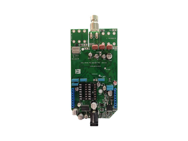
Visual inspection under magnification plus a cure check is usually sufficient, and a sample can be cross sectioned where the repair is critical. Our quality guide describes how a coating defect is classified at gopcb.
Rules That Keep Rework Under Control
The rules that make rework manageable are set at design time: components that are likely to be changed should be identified, the coating should be masked away from them where possible, and the repair material should be recorded with the product. Our design release checklist asks for the coating and the masking scheme to be defined before the board is built, so that a later repair is a planned operation rather than an improvisation.
The work instruction should also state who is authorised to perform a coating repair and what record is kept, because a repair that is not documented cannot be assessed later when a reliability question arises. The record should include the area, the method, the materials and the date.
FAQ
Can a coated board be reworked without removing the coating? Occasionally a small repair can be made through a local opening, but the tool has to reach the joint and the heat has to reach the solder. In most cases the coating has to be removed locally first.
Which removal method is best? Mechanical removal for a small area, chemical or thermal for a larger one, chosen against the coating chemistry. The method that disturbs the surrounding material least is usually the right one.
Does the repair material have to match the original? It has to be compatible, which usually means using the same product or a supplier approved alternative. A different chemistry can be used, but the interface should be tested before it is relied on.