Fiducial Design and Placement for Placement Machines
A fiducial is a reference mark that the placement machine locates optically so that it can align the board to the stencil and to the component image. Without one the machine relies on the board edge, and the board edge is the least accurate feature on the panel.
What the Machine Needs
The machine needs contrast, a defined shape and enough clear area around the mark that the vision system can find its edges. A mark that is half covered by silkscreen is not usable.
The contrast comes from the difference between the copper and the laminate. Our silkscreen notes describe the keep out that protects it.
Size and Clearance
A common size is one millimetre with a clearance of two millimetres, though the exact figure follows the vision system. The clearance matters as much as the size, because the vision system searches a window around the mark.
The window should be free of vias, traces and mask dams. Our registration notes describe the features that share the same area.
Global and Local Fiducials
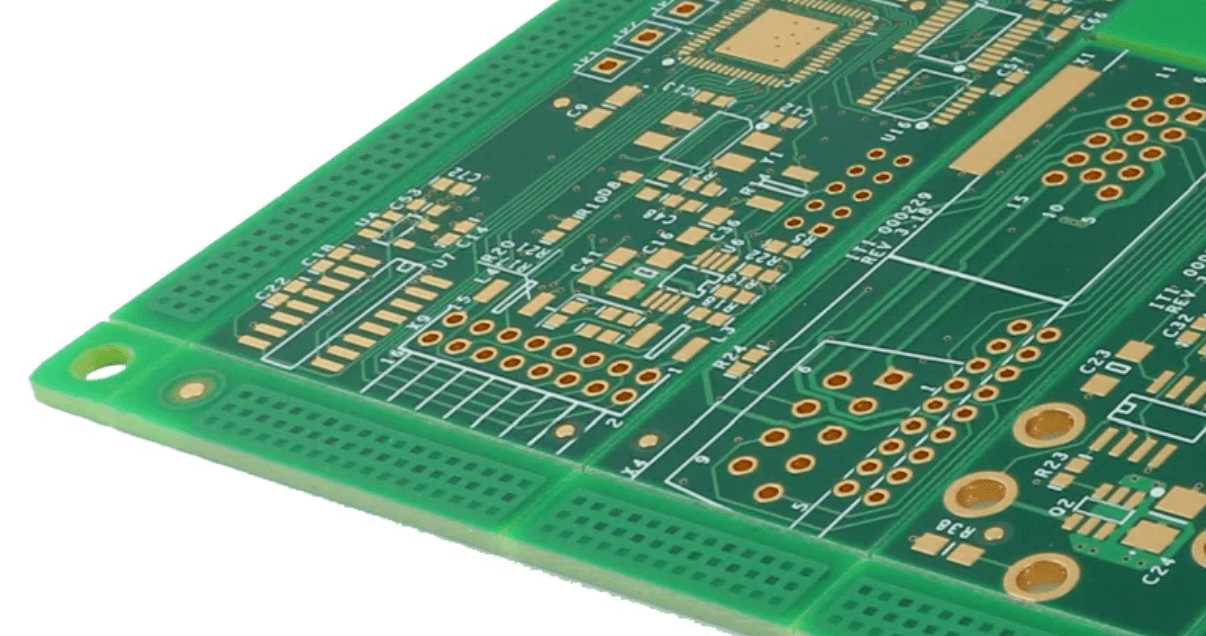
Global fiducials are placed on the panel or on the board corners and align the whole board. Local fiducials are placed near a fine pitch package and align that package against the board it sits on.
Local fiducials compensate for the local distortion that remains after the global alignment. Our placement accuracy notes describe the capability that follows.
Where They Should Not Go
A fiducial should not sit inside a stencil aperture, inside a keep out for a connector, or so close to the board edge that the router nib covers it. It should also not be placed where the panel rail is cut away.
The panel drawing should show every fiducial and its clearance. Our panelization notes describe the arrangement.
Marking the Mask Opening
The fiducial is a copper feature that must be exposed, so the mask opening is larger than the copper. Where the opening is the same size as the copper, the mask covers the edge and the contrast collapses.
The mask drawing should show both dimensions. Our solder mask notes describe the openings that share the layer.
Panel Versus Array Fiducials
Where several boards share a panel, the machine needs at least three fiducials on the panel to establish a coordinate system and it needs board level marks where the array tolerance is tight.
Three marks allow rotation and scaling to be corrected. Our fabrication notes list the points to confirm.
Verification
The verification is a first article run in which the machine reports the fiducial position it found and the residual error after alignment, recorded for the run rather than for a single board.
Our first pass yield notes describe how the data is used.
Process Control and Verification
A stack-up that is drawn rather than described removes most of the ambiguity from a quotation, and it lets the fabricator price the board against the dielectric and copper weights that will actually be used. Where the requirement is not written down, the shop supplies its own default, and the default is chosen for the process rather than for the design.
The measurements that matter are the repeatable ones: conductor width and spacing, annular ring, finished hole size, plating thickness and surface finish are all verifiable on a coupon that travels with the panel. Running a first article through the same checks as the production panel confirms that the two agree, and that comparison is the cheapest form of process control available at prototype stage.
Keeping a sample from the panel turns a dispute into a measurement, because the same coupon can be re-examined by both parties without rebuilding the batch. Reviewing the design before the data is released is cheaper than correcting it after the panel is in the tank, because every step downstream inherits the decision made at the front end.
Documenting the assumption is part of the design work, and a short note on the drawing prevents a question that would otherwise arrive a day later and cost a day of schedule.
Checks Before Release
The checks that matter are the ones performed on the product rather than on a sample kept for the purpose, because a coupon that travels with the panel is the only evidence about that panel. Where a requirement can be measured, it should be measured at the point of manufacture and recorded against the board or the lot it applies to.
A parameter that is set once and never re verified drifts, and the drift is usually discovered by a defect rather than by the record. The tooling, the material and the profile form one system, and a change to any of them should be assessed against the other two before it is released.
Where the process window is narrow, the measurement resolution has to be better than the window, or the data cannot distinguish a good part from a marginal one. A record that identifies the operator, the date and the settings is worth more than a record that identifies only the result.
FAQ
Can a via be used as a fiducial? Sometimes, where it presents a well defined circle with contrast. A dedicated fiducial is more reliable and costs no more to include.
How many fiducials are needed? Three on the panel is the usual minimum, plus local marks near any fine pitch package where the array tolerance is not adequate.
What does gopcb provide for fiducials? We provide fiducials with a stated size and clearance, a mask opening larger than the copper, protection from silkscreen and via keep out, at least three marks per panel, and a first article record of the position found and the residual alignment error.