Conveyor and Magazine Handling Damage on SMT Lines
A production line that is set up correctly and still produces defects usually has a handling problem. Conveyors, magazines, board stops and the way boards are stacked between operations all apply loads that the assembly was not designed for, and the resulting damage appears as cracked components, chipped laminate, worn mask and joints that fail later. This article describes where the loads come from and how to remove them.
How a Conveyor Loads a Board
A conveyor supports a board at its edges and moves it by friction or by a chain that engages the edge. The load path is therefore concentrated along two narrow strips, and anything placed in those strips is at risk. A component that extends into the edge area, a fiducial covered by a rail or a test point under a support finger are all common findings on a line that has handling defects.
Speed changes are as significant as steady motion. A board that accelerates or decelerates quickly slides relative to the belt or the chain, which wears the edge and can dislodge a part. A stop that halts the board abruptly transfers that energy into the board and into whatever is holding it, so the deceleration profile is a process parameter worth controlling.
Edge Support and Board Sag
A wide board supported only at its edges sags in the middle, and the amount depends on thickness, temperature and the weight of the components. Sag changes the board height under the print head, the placement nozzle and the reflow oven, which introduces variation that looks like a machine problem. It also stresses the middle of the board, where a large area array package may be mounted.
The fix is support where the board needs it. Central support rails, adjustable support pins and dedicated fixtures all reduce sag, and they should be set for the specific product rather than left in a default position. The stiffness of the panel itself is a design variable, and the relationship between design and flatness is covered in PCB warpage control.

Magazine Damage and Loading Practice
A magazine is a stack of slots, and every insertion and removal is an opportunity to scrape a board against a slot. Damage occurs when the slot is tight, when the board is inserted at an angle, when the magazine is at the wrong height or when the slot has a burr or a residue of laminate from previous boards.
Good practice is simple to state and easy to audit. The magazine should be at a height where the board slides horizontally, the board should be inserted squarely and fully, and the slot should be inspected for damage at the start of every shift. Overloading, forcing a board or using a magazine with a bent slot is how a small handling error becomes a hidden defect.
Board Stops and Clamping
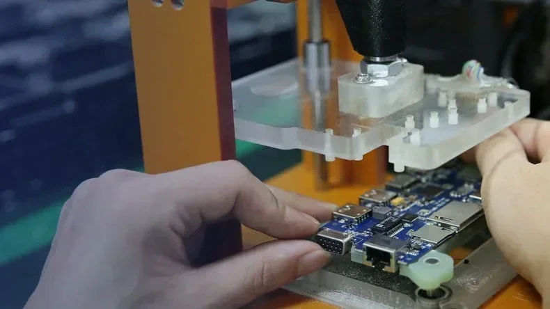
Stops position the board for printing, placement and inspection, and they apply a force each time the board arrives. A stop that is too stiff or a clamp that closes too far deforms the board or the components near the clamp. A clamp that grips a component rather than the laminate can crack a part body without leaving an obvious mark.
The clamping position should therefore be defined by the clearance zone and not by convenience. It should also be verified for each product, because a clamp that was correct for one board outline may land on a component on the next. Where the product mix is wide, recording the clamp setup with the program prevents the kind of error that only appears on one product.
Stacking, Storage and Interleaving
Stacks of boards are a common source of damage between operations. A stack transfers the weight of every board above onto the ones below, and the load concentrates on the tallest feature. Components with a fragile body, connectors and tall capacitors are the usual casualties, and the damage is often a fine crack that becomes an open circuit after thermal cycling.
The remedy is to limit stack height, use a container that supports the boards at their edges, and separate boards with an interleave that is clean and free of particles. Interleave material is part of the process and should be controlled, because a dusty or abrasive sheet puts particles on the surface that later create solder defects.
Tracing a Defect Back to the Handling Step
The most useful investigation technique is to inspect the same feature at several stations. If a mark is present after the conveyor but not before it, the conveyor is implicated, and the same logic applies to a magazine, a clamp or a stack. That requires a defined inspection point and a simple record rather than a full audit.
Photographs make the record usable. A photograph of the damaged feature at each station turns a vague description into evidence that can be compared across products and shifts. The gopcb assembly group keeps a reference set of handling damage images so that a new defect can be classified quickly as familiar or new, and the classification then points to the step that needs attention.
Design Changes That Reduce Handling Risk
Some handling risk can be designed out. A wider clearance zone, no tall components near the edge, fiducials placed outside the rail path and a panel array that gives the conveyor more material all reduce the load the line applies to the product. These changes cost a small amount of board area and are usually cheaper than a containment action.
Where a board is inherently fragile, the answer may be a fixture that supports it through the whole line rather than a change to the board. Fixtures should be treated as production tooling with a defined maintenance interval, because a worn support pin is as damaging as no support at all. Assessing whether the damage is incoming or line induced follows the same logic as the acceptance checks used in judging PCB quality.
Handling Damage on the Reflow Oven and Unloader
The oven is often overlooked because nothing touches the board inside it. In practice the entrance and exit are where most oven related damage occurs, since the board transfers from one conveyor to another and the thermal expansion it has just experienced can leave it slightly different in shape. A rail that is set for a cold board may grip a hot one too tightly, and a support that was correct at room temperature may no longer touch the board at peak temperature.
The unloader presents a different risk. Boards are removed quickly, often stacked or placed on a conveyor that carries them away, and the removal motion is the same kind of edge load as a magazine insertion. Setting the unloader to a slower transfer and confirming that the receiving container supports the board at its edges removes most of the risk. Where damage is suspected at this stage, comparing board condition before and after the oven is the quickest way to confirm it, and the general inspection approach in judging PCB quality provides the criteria for that comparison.
FAQ
Should conveyor speed be reduced to prevent damage? Often, yes. Slower acceleration and deceleration reduces sliding and impact far more than a lower steady speed.
Are magazines interchangeable between products? Not always. Slot width, depth and the presence of a bottom support vary, and a magazine that suits one board can damage another.
How can handling damage be distinguished from assembly defects? By location and by appearance. Handling marks follow the shape of a rail, a clamp or a slot, while assembly defects follow the pattern of the process.