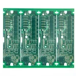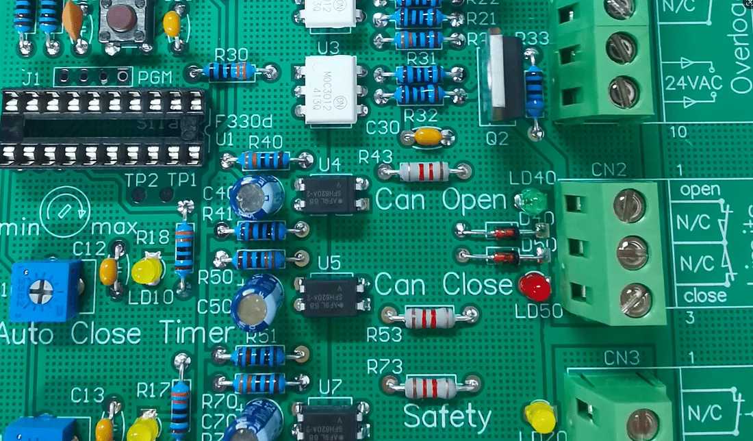
Custom Automotive Controller PCB Manufacturing Guide
A vehicle controller board rarely fails because of one dramatic mistake. It fails because a material choice, a stackup decision, or a lamination window was never matched to the module’s real environment. Custom automotive controller PCB manufacturing starts with that match. The board must survive heat, vibration, moisture, and long operating cycles while carrying dense power and signal circuits. This guide walks through the decisions that shape a controller board, from material selection to final test records.
Automotive control modules differ widely in their electrical and mechanical demands. A powertrain controller needs current capacity and thermal paths. A battery management board needs stable sensing circuits. An ADAS module needs fine routing and controlled impedance. A single standard board cannot serve all three well. Custom manufacturing lets the structure, layer count, copper weight, and process controls follow the application instead of a catalog. Buyers should confirm that this reasoning appears in the supplier’s engineering review, not only in the quotation.
Matching Materials To The Module
Material selection is the first real decision in an automotive controller build. Modules may see a wide temperature range, so the laminate must hold its dimensions and keep its electrical properties. Engineers may choose standard FR-4, high-TG material, low-loss laminate, or heavy-copper construction depending on the load. For power stages, thicker copper improves current carrying and spreads heat. For radar and high-speed links, low-loss dielectric and tight impedance control matter more. The choice should be documented with the thermal and electrical targets it serves.
Material choice also affects assembly and inspection. A high-TG laminate may need a different lamination cycle and reflow profile than standard FR-4. Heavy copper changes etching, plating, and solder mask behavior. Buyers should ask how the chosen material interacts with the rest of the process. A supplier that treats material as an isolated line item often misses those interactions. Strong quality management starts with these links being written down before tooling begins.
Stackup Choices That Hold Up
Modern controllers need several power, ground, signal, and communication layers. A well-planned multilayer stackup separates noisy power switching from sensitive sensing and keeps reference planes continuous. Layer order affects impedance, crosstalk, thermal spreading, and manufacturability at the same time. Engineers should fix the stackup before routing is complete, because later changes ripple through drilling, lamination, and test. The stackup drawing should state dielectric thickness, copper weight, and target impedance for each critical net.
High-density modules may need microvias, blind vias, and sequential lamination to fit the routing. HDI structures shorten connections and free space around fine-pitch components. They also add process steps and inspection points, so the benefit must justify the cost. For compact ADAS or communication boards, the trade often pays. For simpler body controllers, a conventional multilayer board may be the better buy. The decision belongs to the application, not to a preference for advanced technology.
Lamination And Drilling Risk
Lamination bonds cores and prepreg into one solid board. The result depends on temperature, pressure, heating rate, cooling rate, and resin flow. Poor control can cause layer misalignment, delamination, voids, resin starvation, or warpage. Each of these problems can shift drilling accuracy and dielectric thickness later. Automotive boards face added stress from thermal cycling, so a stable lamination process protects long-term reliability. Buyers should ask for the press profile and the registration checks used on similar builds.
Resin starvation deserves separate attention because it hides inside the board. When prepreg flow is too low for the copper pattern, gaps remain between layers and fill poorly around traces. The board may pass a visual check and still fail after thermal cycling in the vehicle. Press cycles should be matched to copper distribution, and heavy-copper zones need enough resin to fill the space. Buyers should ask how the supplier verifies fill on boards with mixed copper density, and whether coupons are cut for cross-section review.
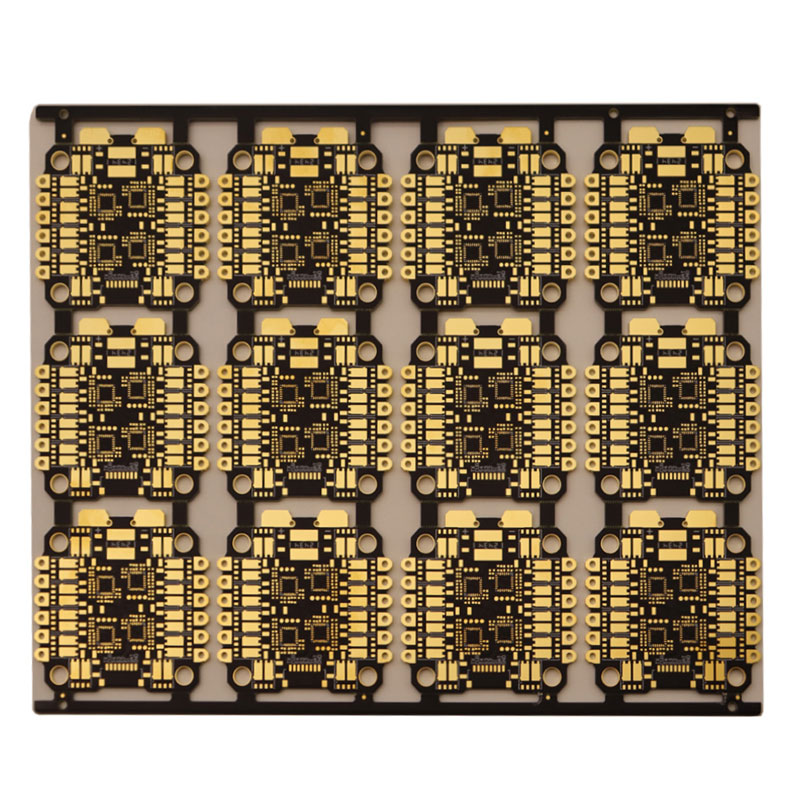
Drilling follows lamination, and its quality decides plating reliability. Hole-wall quality, drill registration, and debris removal all affect the copper connection between layers. Small errors in inner-layer registration grow worse after pressing, so the two processes must be reviewed together. Plating then builds the conductive wall and surface copper. Uniform thickness and clean hole walls support both current capacity and mechanical strength. A supplier should show how it monitors these parameters across a production lot, not only on a first article.
Drill wear is a quiet cause of via defects on long runs. A worn bit heats the hole wall, smears resin, and leaves a rough surface that plating cannot cover evenly. The result is a weak barrel that passes electrical test and cracks later under thermal stress. Suppliers should track drill life by hole count and inspect hole walls on a sampling basis.
Buyers can ask for the drill log and the smear review records, which show whether the bit change schedule is followed on the floor rather than written in a procedure.
Surface Finish And Solderability
The surface finish protects exposed copper and prepares the board for assembly. ENIG, ENEPIG, OSP, and other finishes each suit different needs. The right choice depends on solderability, component pitch, storage conditions, and the expected reflow cycles. A finish that works for a simple board may cause problems on a fine-pitch controller with a long assembly schedule. Buyers should state storage and handling expectations clearly. The finish decision should be tied to the assembly plan rather than picked by habit.
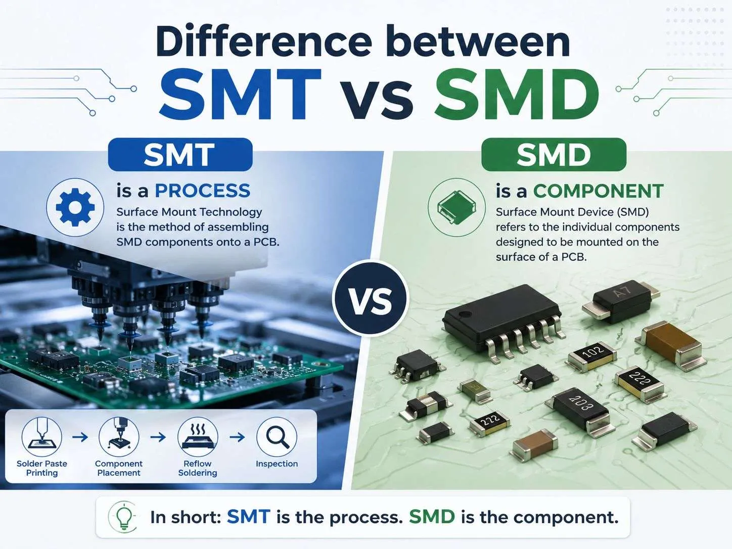
Finish quality also affects inspection. Contamination, oxidation, or uneven thickness can create solder defects that appear only at assembly. This is why finish inspection belongs in the fabrication record. When the board moves to SMT PCB assembly, the paste print and reflow profile must match the finish and the component mix. Early coordination between fabrication and assembly prevents many avoidable defects and keeps the first build close to the final process.
Inspection And Test Coverage
Quality control in automotive work must cover incoming material, each process step, and final verification. Automated optical inspection catches pattern and placement errors. Electrical testing confirms continuity and isolation. X-ray inspection checks hidden joints and via quality where needed. Impedance testing verifies controlled lines against the stackup targets. Dimensional checks confirm board outline and hole positions. Solderability and finish inspection protect the assembly stage. The test plan should name the checks, the sampling, and the acceptance limits before production starts.
Test coverage is only useful when results feed back into the process. A failing impedance line should trigger a stackup or etch review, not just a scrap decision. A repeated via defect should send engineers back to drilling and plating parameters. This closed loop is what makes a process repeatable across lots. Buyers reviewing PCBA testing should ask how failures are traced to process causes. A supplier that records causes and fixes them will show a falling defect trend over time.
Traceability turns those records into a working tool. Each lot should link the laminate batch, prepreg roll, drill program, plating line, and test results to a single identifier. When a field return arrives months later, that link shows which process step differed from the approved baseline. Without it, engineers can only guess at the cause and may repeat the fault on the next order. Buyers should confirm that traceability covers materials and process parameters, not just the final serial number on the board.
Prototype To Production Flow
Prototypes are the cheapest place to find problems. A small first batch reveals pad geometry issues, component tolerance problems, and process behavior before volume is committed. Rapid PCBA prototyping lets engineers test the controller in its real environment and adjust the design while changes are still inexpensive. The first article should be approved against written requirements, process settings, and inspection records. Those records become the baseline for every later lot.
Moving from prototype to volume requires more than a larger order. Fixtures, test programs, stencils, and assembly sequences must scale with the design. Component sourcing must be stable, and alternates should be approved in advance. Integrated PCB assembly under one roof simplifies communication between fabrication and assembly teams. It also shortens the path from a design question to a verified answer. Buyers should confirm who owns each step and how changes are communicated before the volume order is placed.
What Buyers Should Verify
A supplier audit should focus on evidence, not claims. Ask for the stackup drawing, material certificates, press profiles, and plating records. Request the inspection plan and sample test reports from a comparable automotive build. Check how nonconforming boards are handled and how corrective actions are verified. Confirm that traceability links materials, process parameters, and test results to each lot. These documents show whether the process is controlled in daily practice or only described in a brochure.
Ask also how the supplier handles a change after approval. A new laminate source, a different prepreg lot, or a revised drill program can shift results without any visible design change. A controlled process records the change, reviews its effect, and re-approves the first article when the risk is real. Buyers should see that change log and know who signs it. A supplier that cannot describe this flow is likely to introduce variation quietly, and the first sign will be a field failure.
The practical takeaway is simple. Start with the module’s environment and electrical targets, then let material, stackup, copper weight, and finish follow from them. Fix the process windows before the first article, record what actually ran, and compare each lot against that baseline. A custom automotive controller board is only as reliable as the decisions behind it. Buyers who ask for those decisions in writing get a board they can trust in the vehicle, and a supplier relationship that holds up across repeat orders.