Power Monitoring Systems: Custom PCB Manufacturing
Power monitoring hardware sits at the edge of the electrical network. It measures voltage, current, temperature and other operating values. The board underneath carries sensitive analog channels and digital communication circuits at the same time. A generic circuit board rarely suits that mix. Custom PCB manufacturing for power monitoring systems adapts the stackup, materials, grounding and protection to the real installation. The sections below explain the decisions that matter and what a buyer should verify before release.
Operating Conditions That Shape Design
Power monitoring equipment often runs continuously in substations, distribution rooms and outdoor cabinets. High-voltage equipment nearby generates strong electromagnetic fields that couple into measurement circuits. Temperature swings, humidity, vibration and electrical transients add further stress. These conditions place higher demands on the board than most consumer electronics face. The design review should start from the installation environment rather than from a standard template. Recording those conditions early keeps later choices consistent.
A board that works on the bench may fail in the cabinet. Field conditions combine noise, heat and moisture in ways a lab test rarely reproduces. Engineers should list the expected temperature range, humidity level, vibration source and interference risk before layout begins. That list becomes the reference for material selection, coating choice and mechanical design. Buyers can ask for this list during quotation and compare it against the proposed build. Clear inputs reduce rework later in the project.
Transient events deserve their own line in that list. A switching surge can couple into sensor wiring and reach the analog front end before any filter reacts. Layout should keep surge paths short and separate from low-level signal traces. Grounding at the connector entry point decides how much energy reaches the board. Buyers should ask how the design handles surge return paths and whether the enclosure provides a clean earth reference. These questions cost nothing at review and prevent field failures later.
Electromagnetic Interference Protection
Interference resistance is one of the first considerations in a power monitoring board. Sensitive circuits acquire low-level voltage, current, temperature and sensor signals, so small coupled noise can shift readings. A customized layout can use dedicated ground planes, structured power distribution and careful signal routing to isolate those paths. Multilayer constructions help by placing reference planes close to signal layers. Proper grounding and routing protect measurement accuracy and reduce communication errors. These choices belong in the stackup plan, not in a late layout fix.
Shielding strategy depends on the enclosure and the cable entry points. Connectors that bring sensor wiring onto the board can act as antennas for outside noise. Filtering and careful return-path design at those entry points limit what reaches the analog front end. The board outline, mounting holes and connector positions should be agreed with the mechanical team early. A layout that ignores the enclosure usually needs a second revision. Checking these interfaces against the PCB design and layout rules before release saves a costly respin.
Thermal Stability and Material Choice
Outdoor installations and equipment cabinets see substantial temperature change across the year. Repeated expansion and contraction stresses the laminate, the plated holes and the solder joints. High-Tg laminate materials may be selected where improved thermal stability is needed. Tg means the glass transition temperature, the point where the resin softens. Material choice should match the expected operating temperature, copper structure, board thickness and layer count. The assembly process also matters, because reflow exposure adds its own thermal load.
Documenting these figures keeps design, assembly and test teams working from the same numbers.

For multilayer boards, lamination parameters must be controlled to limit dimensional change. Temperature, pressure, heating and cooling rates, resin flow and layer alignment all affect dielectric thickness and bonding quality. Poor control shows up as delamination, warpage or drifting impedance. Delamination means the layers separate, and warpage means the board twists or bows. The stackup should be fixed before production and repeated on every lot. Buyers should ask how the fabricator records lamination profiles and how deviations are handled. Consistent process records are the practical proof of control.
Moisture and Corrosion Protection
Humidity and salt contamination accelerate copper oxidation and degrade exposed conductive surfaces. Coastal sites, industrial plants and outdoor cabinets carry the highest risk. Protective coatings, suitable surface finishes and optimized solder mask processes can improve environmental resistance. Enclosure design and gasket placement also influence what reaches the board. The protection strategy should follow the actual environment rather than a single default. Applying a coating everywhere adds cost without always adding value.
Coating choice interacts with assembly and repair. Some coatings complicate rework and connector masking, so the process plan should cover both. Surface finish selection affects solderability and shelf life as well. Buyers should confirm that the finish suits the storage period and the assembly schedule. Suppliers who handle coating and assembly together can align these steps. The component procurement process should also confirm that purchased parts tolerate the chosen coating and cleaning steps.
Customization Across Monitoring Applications
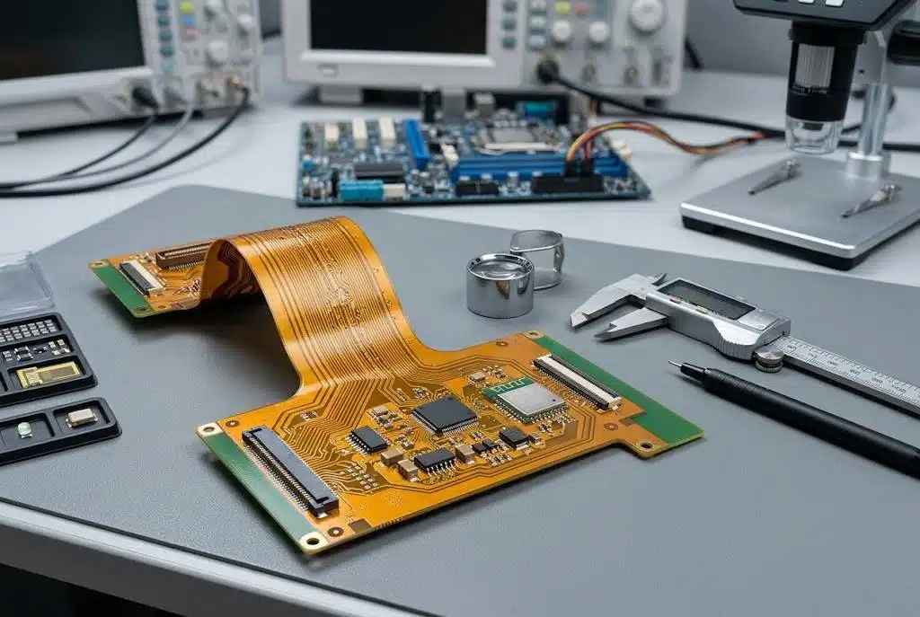
Transmission tower terminals must survive wind, vibration, rain and long outdoor exposure. The board may need extra mechanical strength, robust mounting and reliable solder joints. Rigid-flex or flexible structures can help where installation space is tight or slight movement occurs. Distribution room units pack many functions into a small enclosure, so multilayer construction integrates sensor inputs, communication and power circuits on one board. Renewable energy equipment adds low standby power and stable sensor acquisition to the requirement list. Each case changes the board architecture.
Compact units must balance component density, thermal management, creepage and clearance, and serviceability. Creepage is the surface distance between conductors, and clearance is the air gap. Separate signal, power and ground structures help organize complex circuits and limit coupling. A high-volume PCB assembly plan should be reviewed alongside the layout, because placement density affects yield. Modular board architecture can simplify maintenance, since a failed function board may be replaced instead of the whole unit. These decisions are cheaper at design stage than after tooling.
Fabrication and Interconnection Control
Plated through-holes connect conductive layers in a multilayer board, and their reliability matters when power and signal layers share the same structure. Controlled drilling, hole-wall preparation, electroless copper deposition and electrolytic plating build those connections. Copper thickness and via structure should follow the required current capacity and thermal conditions. Uneven copper distribution can create localized heating. Process drift in plating or drilling turns into yield loss quickly, so the fabricator should monitor both. First-article data should confirm the agreed limits.
Drilling problems appear in predictable ways. A worn bit tears the hole wall and leaves a rough surface that plating cannot cover evenly. Misregistration shifts the hole away from its pad and cuts the annular ring, the copper ring around the hole. Both faults pass a quick visual check and fail later in the field. Buyers should ask how often drill bits are changed and how registration is measured. Cross-section data from the first article shows whether the plating is sound.
Quality control covers manufacturing defects and electrical performance together. Inspection may include automated optical inspection, dimensional checks, X-ray review, cross-section analysis and electrical test. Full electrical testing verifies continuity, insulation and overall integrity before shipment. A structured quality management system keeps these records with the lot. Engineering review and DFM analysis before production catch spacing, registration and stackup problems while they are still cheap to fix. Buyers should request the inspection plan with the quotation.
Signal Integrity and Controlled Impedance
Modern monitoring units combine power measurement with digital communication and remote data interfaces. Signal integrity therefore becomes part of PCB engineering, not an afterthought. A controlled impedance board holds predictable transmission-line behavior by managing trace width, copper thickness, dielectric thickness and reference-plane configuration. Impedance is the resistance a trace presents to a high-speed signal. For sensitive interfaces, impedance-controlled routing reduces reflection and keeps transmission consistent. The fabricator and design team should agree the stackup and tolerances before production. Multilayer monitoring boards need this agreement most.
Prototype builds give engineers a chance to measure before volume commitment. A rapid PCBA prototyping stage reveals thermal behavior, mechanical fit and signal quality on real hardware. Findings from that stage should feed back into the production documents. Changes in material, stencil or profile must be recorded and rechecked. Buyers should treat the prototype as a validation step rather than a formality. It is the cheapest place to find a mistake.
What Buyers Should Verify
Before release, confirm the stackup, material grade, copper weight and surface finish against the environment. Ask how lamination, drilling and plating parameters are recorded, and request the inspection plan. Check that impedance targets are stated with tolerances and that test coverage matches the circuit complexity. Confirm the coating and masking plan suits assembly and repair. Finally, verify that first-article results are kept with the lot record. These checks cost little at the start and protect the schedule once production begins.
Ask for the process sheet that lists each step and its control limits. A supplier who cannot show this document is guessing at consistency. Confirm who signs off on deviations and how a changed material is approved. Require the lot record to travel with the boards, so a field return can be traced to its build data. These records turn a quotation into evidence. They also make a repeat order far easier to place with confidence.