Rail Transit Control Board PCB Reliability Guide
Rail transit control boards manage traction, braking, signaling, and monitoring functions on moving trains and trackside cabinets. The PCB inside each unit carries those functions through vibration, heat, humidity, and long service cycles. A rail transit control board PCB therefore needs more than a standard industrial build. Design choices, material selection, fabrication control, and assembly quality all decide whether the board survives its environment. This guide explains the decisions that matter and what buyers should verify.
Reliability in railway electronics rarely comes from one clever feature. It comes from consistent process control across fabrication and assembly. Small drifts in plating, layer registration, or solder volume can turn into field failures years later. Engineers and buyers should treat the PCB as a system tied to its enclosure, connectors, and thermal path. The sections below cover requirements, applications, processes, testing, and assembly in practical terms. Each part points to the checks that keep a production lot predictable.
Operating Conditions That Shape Design
Railway equipment faces continuous vibration from track joints, acceleration, and braking. Repeated mechanical stress can crack solder joints, damage vias, and weaken laminate bonds over time. The PCB structure should resist these loads through suitable thickness, copper balance, and via design. Component attachment also matters, especially for heavy parts such as relays and connectors. Engineers should review mounting points and stiffening options early. A board that passes bench tests may still fail if mechanical stress is ignored during layout.
Temperature swings add another layer of stress. Trackside cabinets can heat under direct sun and cool sharply at night, while onboard electronics generate their own heat. Materials expand and contract at different rates, so repeated thermal cycling loads interconnections and plated holes. High-Tg laminates help where thermal stability is a design priority. The stackup should also balance copper distribution to reduce warpage. Thermal vias and copper planes can spread heat away from hot components. These choices belong in the design review, not in a late fix.
Stackup Choices and Signal Behavior
Electromagnetic compatibility is a core requirement for railway control electronics. Traction motors, power converters, and signaling equipment all produce interference. A control board must resist external noise and limit its own emissions. Grounding, return-current paths, and layer arrangement work together here. A multilayer stackup can give sensitive signals dedicated layers and predictable return paths. Power and ground planes also reduce loop area. Engineers should define these structures before routing begins, because retrofitting them later usually costs more.
Signal integrity matters when control boards include high-speed communication interfaces. Impedance control, trace spacing, and reference-plane continuity all affect signal quality. Breaks in the return path cause reflections and radiation, which can disturb nearby circuits. Differential pairs should be routed with consistent spacing and length. Connector pinouts and layer transitions deserve the same attention. For station interlocking and section signaling boards, clean signal behavior supports reliable command transfer. Buyers should ask for impedance reports where controlled structures are specified.
Railway Control Board Applications
Onboard control boards support traction control, braking, door operation, passenger information, and equipment monitoring. Each function places different demands on the PCB. Traction electronics may carry higher currents and generate significant heat, so copper weight and thermal design need review. Door control modules often face tight space limits and repeated mechanical cycles. Compact layouts must still leave room for robust connections. Passenger information and communication boards lean toward higher routing density and signal integrity. A single train may use several board types, each with its own verification plan.
Signaling systems manage train separation and route safety, so their boards must transmit signals reliably over long periods. Section signaling boards process information tied to track sections and train movement. Station interlocking systems coordinate switches, signals, and other infrastructure across many channels. These boards often need high-density multilayer structures to organize different circuit functions. Dedicated layers help separate noisy power circuits from sensitive logic. Connector count and interface protection also shape the layout. Engineers should confirm that the fabrication house can hold the required registration and trace tolerances.
Trackside Equipment Protection
Trackside cabinets stay outdoors for years and face rain, humidity, dust, and temperature change. Switch machine controllers, overhead-line monitoring units, and detection systems all fall into this group. Moisture protection starts with material choice, solder mask quality, and surface finish. Enclosure design and conformal coating add further barriers where the architecture allows. Coating should be specified with the right coverage areas and cure conditions. Maintenance access also matters, because field service is harder than bench repair. These factors belong in the drawing package and the inspection plan.
Long-term reliability is critical because trackside equipment is spread across wide areas. A field failure can disrupt service and require a costly visit. Consistent materials and tightly controlled processes reduce that risk. Quality control should cover fabrication, interconnections, plating, solderability, and electrical testing. Dimensional inspection confirms that connectors and mounting features fit. Buyers should keep lot records so that any later issue can be traced to its source. A disciplined quality management system supports this traceability from incoming material to final shipment.
Fabrication Process Control
Material selection should follow the operating temperature, mechanical stress, electrical needs, and moisture exposure of the application. Standard FR-4 suits many control boards, while high-Tg laminates help where thermal cycling is severe. High-performance materials may be needed for demanding signal or thermal conditions. The laminate should be evaluated together with layer count, copper thickness, and dielectric thickness. Buyers should confirm that the chosen material is available for the full production run. Substitution without review can change electrical and mechanical behavior.
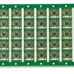
Precision fabrication keeps dimensions consistent across lots. Trace width, spacing, copper thickness, drilling accuracy, and layer registration all need control. Multilayer boards are especially sensitive to layer alignment, because misregistration affects connectivity, via structures, and impedance. Surface finish selection follows the assembly process and the service environment. ENIG, lead-free HASL, OSP, immersion tin, immersion silver, and ENEPIG each offer different solderability and corrosion behavior. The finish should match the expected storage time and the number of assembly passes. Buyers should state these conditions in the purchase documents.
Testing and Assembly Checks
Finished boards should pass inspection and electrical testing before shipment. Visual and dimensional checks confirm appearance and fit. Automated optical inspection catches pattern defects. Electrical continuity and insulation resistance testing find opens, shorts, and leakage paths. Dielectric withstand testing verifies isolation where required. Impedance testing applies to controlled structures. Solderability evaluation confirms that the finish will wet properly during assembly. Project specifications may add reliability tests such as thermal cycling. Each test should have a defined acceptance limit and a recorded result.
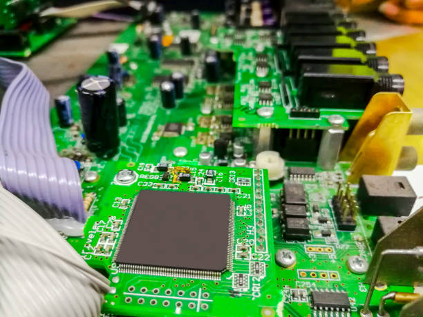
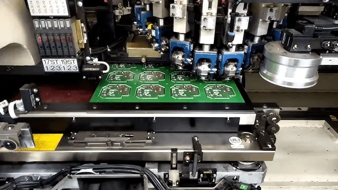
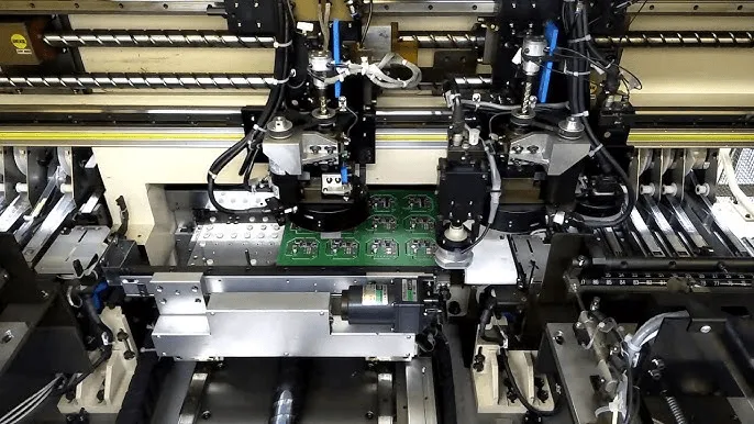
Assembly quality decides whether a good bare board becomes a reliable control unit. Rail boards often mix fine-pitch surface-mount parts with connectors, relays, and power devices. Placement accuracy, solder-joint quality, and reflow profiles all need control. Through-hole soldering and press-fit connectors require their own process settings. Inspection should follow assembly, and functional testing should confirm the completed unit. Where the design calls for it, conformal coating protects against moisture and contamination. A partner offering SMT PCB assembly and through-hole work under one roof reduces handoff risk.
Design Review and Production Records
Reliability begins in design, before any panel is built. Engineers should review the operating environment, thermal path, mechanical mounting, and EMC needs together. Component placement affects both heat and routing. Power distribution and ground-plane design shape noise behavior. High-current traces, differential pairs, and controlled impedance need early definition. Creepage and clearance rules apply to higher-voltage sections. Connector positioning should suit the harness and the enclosure. An early review with the fabricator can catch features that are hard to build or inspect.
Prototypes are the cheapest place to find problems. A small pilot batch reveals pad geometry issues, component tolerances, and process behavior before volume commitment. Rapid PCBA prototyping helps teams test these details early and adjust the design. Records should follow every build. The factory should note which program ran, which materials were used, and what inspection found. When a field return arrives, that record speeds up the cause analysis. Buyers should ask for these documents as a routine part of each order, not as a special request.
Assembly and test records complete the picture. Functional testing verifies that the board performs its intended control function. In-circuit testing checks component values and connections. PCBA testing should be planned alongside the design so that test points and fixtures are ready. For repeat orders, the same test plan should run unless a change is approved. Changes in components, stencils, or profiles should feed back into the documentation. This discipline keeps the second lot as good as the first and protects the delivery schedule.
Buyer Verification Points
When comparing suppliers, buyers should look beyond the unit price. Ask how the factory controls layer registration, plating thickness, and surface finish. Request the stackup and material certificates for the lot. Confirm which tests run on every board and which run by sample. Ask how assembly changes are approved and recorded. Check that the supplier can support both bare board fabrication and PCB assembly if you need a single point of responsibility. Clear answers to these questions show whether the process is controlled in practice.
Keep the review points visible during first-article approval. Confirm the material, stackup, copper weight, and finish against the drawing. Verify that impedance, continuity, and insulation results meet the stated limits. Check the assembly inspection data and the functional test report. Record any deviation and close it before the next build. On repeat orders, compare the new lot against the approved first article. This simple routine catches drift early, while fixes are still cheap. It also gives the buyer a documented basis for accepting each shipment.