Drone Mainboard vs Flight Controller PCB: What Is the Difference?
Two Boards with Very Different Jobs
In a drone the electronics are usually split between a flight controller and a mainboard, and the two are designed with opposite priorities. The flight controller exists to keep the aircraft stable, which means it must measure rotation extremely accurately and react within a fraction of a millisecond. The mainboard distributes power, routes video and telemetry, and manages the payload, which means it deals with high currents, connectors and whatever the mission requires. Confusing the two leads to layouts that either compromise flight stability or make the power path unnecessarily difficult.
What a Flight Controller Does
A flight controller reads an inertial measurement unit, fuses it with a barometer, magnetometer and satellite data, runs the stabilisation loop and outputs motor commands to the electronic speed controllers. The control loop typically runs at one to eight kilohertz, so the whole signal chain has to be deterministic and low latency. The sensors are the delicate part. A gyroscope that resolves fractions of a degree per second will register noise from a switching regulator, a vibrating wire or a poorly placed component just as readily as it registers rotation, and that noise becomes visible as motor jitter or as a drifting attitude estimate.
What a Mainboard Does
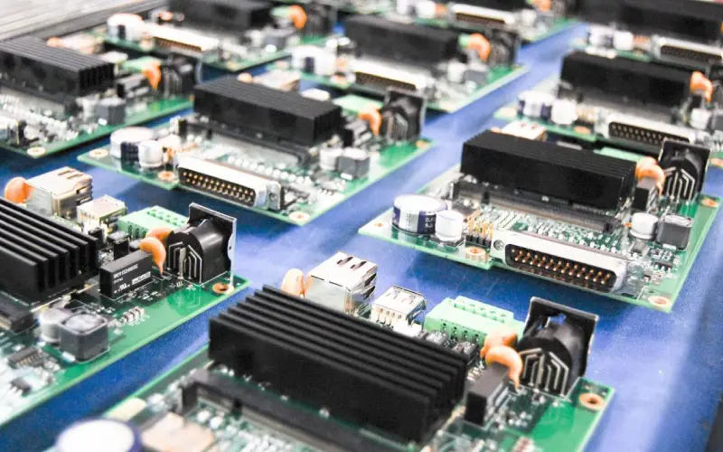
The mainboard, sometimes called the carrier or distribution board, is the aircraft’s electrical hub. It carries the battery connector and the main power path, distributes power to the speed controllers, provides regulated rails for the flight controller and the radio, routes video from the camera, carries telemetry and payload interfaces, and often hosts the gimbal or the onboard computer. It is a power and interface board, and its design is dominated by current capacity, connector placement and thermal management rather than by measurement precision.

The Key Differences
Function. The flight controller stabilises the aircraft; the mainboard distributes power and routes signals. Precision. The flight controller needs a low noise analogue environment for the inertial sensors; the mainboard tolerates far more. Current. The mainboard may carry tens of amps; the flight controller carries milliamps. Vibration. The flight controller is critically sensitive to vibration and usually sits on dampers; the mainboard is far less affected. Layer count. Flight controllers are often four to six layers in a very small outline; mainboards are typically four layers but can be larger and thinner. Connectors. The mainboard has the heavy connectors and the battery interface; the flight controller has fine pitch sensor and signal connections. Update cycle. The flight controller is often a purchased module with firmware, while the mainboard is more likely to be a custom design.
Design Requirements for the Flight Controller
Sensor placement. Put the IMU at the physical centre of rotation if possible, and keep it away from the motors, the speed controller wiring and any switching regulator. Low noise supply. Feed the IMU from a dedicated low noise linear regulator with solid decoupling, and keep switching nodes far from the sensor and its traces. Vibration. Use a rigid mounting and soft damping, and avoid long unsupported board sections that can resonate. On the layout, keep the inertial sensor close to the mounting points so the board does not flex under it. Grounding. Provide a solid ground plane under the sensor and the analogue section, and keep digital return currents out of that area. Thermal drift. Temperature gradients across the IMU cause bias drift, so avoid placing heat sources near the sensor and consider a thermal barrier. Real time routing. Keep the SPI or I2C link to the sensor short and direct, and avoid any multiplexing that adds latency.
Design Requirements for the Mainboard
Current path. Size the copper for the maximum continuous current with an acceptable temperature rise, and use heavy copper or a busbar where the current is highest. Connector placement. Connectors dominate the mechanical layout, so place them where the harnesses naturally run and give each one strain relief. Thermal. The speed controller interfaces, the power regulators and the battery connector are heat sources; spread them out and provide copper area. EMI. The speed controllers switch high currents with fast edges, so their wiring radiates; keep the sensitive video and radio links away from those paths and filter them at the connector. Video integrity. Analogue or digital video links need a controlled impedance path and a continuous ground reference, and they must not share a return with the motor current. Weight. Every gram matters, so the board thickness and the copper weight are chosen as a balance of current capacity, stiffness and mass.
Manufacturing Considerations
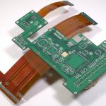
Drone boards are usually thin, lightweight and densely packed, which makes panel handling and warpage control important. High-Tg laminate is standard because the boards sit in sunlight and near hot electronics. Where the mainboard carries high current, heavy copper is used, and where the frame requires it, rigid-flex can replace a wiring harness and remove a connector. Conformal coating is common, since drones operate outdoors and are exposed to humidity and dust. Assembly is dominated by the fine pitch sensors, the connectors and, on the mainboard, any heavy current joints that may need selective soldering or reinforcement.
Both boards end at the same fabrication house, so they should be planned together. Review how PCB manufacturing handles thin, light and heavy copper boards, apply the sensor and power rules in your PCB design and layout, and check the design and manufacturing considerations before release. A prototype PCB assembly run with a flight test in stabilised mode is the only way to prove the sensor layout.
FAQ
Can one board do both jobs? Sometimes, on small drones, the flight controller and the power distribution are combined, but the layout has to protect the sensors from the power stage.
Why is the IMU so sensitive? Because it measures very small rotations, so electrical noise and vibration appear as real motion in the control loop.
Does the mainboard need heavy copper? If it carries the battery and motor current, yes, and the copper weight is set by the maximum continuous current.
Is conformal coating necessary? For outdoor use it is strongly recommended, because humidity and dust degrade high impedance and connector surfaces.
Conclusion
A drone mainboard and a flight controller PCB look similar but are designed for opposite priorities. The flight controller protects a very small sensor signal and must be electrically and mechanically quiet; the mainboard moves large currents and routes the aircraft’s interfaces. Keep the precision and the power separate, damp the inertial sensor, size the copper for the current and filter the video path. Done that way in 2026, the aircraft will hold attitude smoothly while the mission electronics do their work.