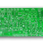
Duroid PCB Guide: Cost, Design Rules & Supplier Selection
If you’re designing RF, microwave, radar, or satellite communication equipment, choosing the right PCB material is critical. Duroid PCBs are renowned for their extremely low dielectric loss and high-frequency stability, making them a top choice for engineers developing advanced wireless systems. This guide covers Duroid PCB manufacturing, design rules, cost factors, and how to select the best supplier in China.
1. Introduction to Duroid PCBs
In high-frequency applications like RF, microwave, and satellite communications, material selection is critical. Duroid PCBs are widely used in:
- 5G base stations and antenna systems
- Radar and defense electronics
- Aerospace communication equipment
- RF amplifiers and power systems
- High-frequency test instruments
They ensure excellent signal integrity and are a preferred choice for advanced wireless device development.

2. Why Duroid is Ideal for High-Frequency PCBs
- Ultra-low dielectric loss – reduces signal attenuation
- Stable dielectric constant – ensures consistent impedance
- High moisture resistance – performs well in harsh environments
- Excellent thermal performance – suitable for high-power applications
- Better dimensional stability
These properties make Duroid significantly superior to FR4 in GHz-level applications.
3. Duroid PCB Manufacturing Process
- Special handling for PTFE flexible material to avoid warpage
- Precision drilling to minimize burrs and wall damage
- Copper adhesion treatment for better bonding
- Vacuum lamination to reduce voids
- Strict tolerance control for high-frequency performance
Manufacturer experience directly impacts product quality.
4. Key Design Rules for Duroid PCBs
- Precise impedance control – target ±5% or better; use simulation software
- Trace width and spacing – based on Dk, frequency, and signal speed; microstrip vs. stripline differ
- High-frequency via design – back-drilling to reduce parasitic effects; blind or filled vias to minimize reflections
- Copper thickness & surface finish – 1–3 oz for power layers; ENIG or immersion silver preferred
Good design = lower return loss + higher signal efficiency. Explore GoPCB’s design & layout services →

5. Duroid PCB Cost Analysis
Duroid materials are more expensive due to:
- Costly PTFE substrate
- High-frequency manufacturing difficulty
- RF testing requirements
Cost Drivers
| Factor | Impact |
|---|---|
| Material grade | Higher grade = higher cost |
| Layer count & thickness | Significant increase with more layers |
| Impedance control & testing | Adds production cost |
| Batch size | Higher unit cost for small batches |
2025 Reference Pricing
| Product Type | Price Range |
|---|---|
| 2-layer Duroid 5880 prototype | $500 – $1,200/batch |
| 4–6 layer communication boards | $1,000 – $3,000+/batch |
| Multilayer radar/satellite PCBs | $3,000 – $10,000+ |
Volume production significantly reduces unit cost.
6. How to Choose the Right Duroid Material
| Material | Dielectric Constant | Recommended Application |
|---|---|---|
| 5880 | 2.20 | Antennas, satellite systems |
| 6002 | 2.94 | Aerospace |
| 6035HTC | High thermal conductivity | Power RF modules |
| 6202 | Strong mechanical properties | High-vibration environments |
7. Duroid vs. FR4 Comparison
| Property | Duroid PCB | FR4 PCB |
|---|---|---|
| High-frequency loss | Very low | High |
| Signal integrity | Excellent | Moderate |
| Cost | High | Low |
8. Common Challenges in Duroid PCB Manufacturing
- Poor copper adhesion
- CTE mismatch causing instability
- Burrs and layer slippage during drilling
Experienced manufacturers can avoid these quality defects. Learn about GoPCB’s manufacturing capabilities →
9. Duroid PCB Testing Procedures
- TDR impedance testing
- VNA (vector network analyzer) measurements
- High-frequency insertion loss testing
- Thermal shock and environmental reliability tests
10. How to Choose a Reliable Duroid PCB Supplier
- Experience with RF PCB manufacturing
- Authorized Rogers material sourcing channels
- Comprehensive high-frequency testing capabilities
- Quick-turn prototyping and stable volume production
- ISO9001 / IATF16949 certifications
11. GoPCB: Premium Duroid PCB Manufacturer
- Prototyping from $500/project
- 5–10 day quick-turn service
- Supports orders from 1 piece
- Controlled impedance + RF testing + DFM support
- Applications: aerospace, radar, satellite communications
GoPCB helps engineers reduce development risk and shorten delivery cycles. Get a prototype quote → · Low-volume assembly
12. Conclusion
Duroid PCBs offer:
- High-frequency stability
- Ultra-low loss
- Excellent signal integrity
They are the best choice for RF and communication equipment. Selecting the right material and an experienced manufacturer like GoPCB will significantly enhance product performance and reliability.
13. FAQ
- Q1: Can Duroid be mixed with FR4?
A1: Yes, often used to reduce cost while maintaining high-frequency performance in critical areas. - Q2: What is the minimum order quantity?
A2: Prototyping can start from as low as 1 piece. - Q3: What industries use Duroid PCBs most?
A3: Aerospace, satellite communications, defense electronics, and 5G equipment manufacturing.
📡 Contact GoPCB for your Duroid PCB project — high-frequency, reliable, and built for performance.
GoPCB Home · Turnkey Assembly · SMT Assembly · Component Procurement