Embedded Passives Technology PCB Design and Manufacturing Process Collaboration
Embedded passives technology represents one of the key paths for high-density interconnect, or HDI, PCB evolving toward system-in-package, or SiP. This technology directly integrates passive components such as capacitors and resistors into the dielectric layers of multilayer printed circuit boards, rather than using traditional surface mount technology, or SMT. Its core value lies in significantly improving high-frequency signal integrity, reducing parasitic inductance and equivalent series resistance, or ESR, saving board space, and enhancing thermal management capability. Taking a certain 5G millimeter-wave RF front-end module as an example, by embedding a 100 pF plus or minus 5 percent BaTiO3-based ceramic capacitor array of 0.3 mm by 0.3 mm by 25 micrometers between layers L2 and L3, the power decoupling response bandwidth is extended to more than 12 GHz, 3.8 times higher than traditional 0201 package capacitors. It also reduces 6 SMT solder joints and corresponding trace lengths, effectively suppressing power delivery network, or PDN, resonance peaks.

Material System and Dielectric Layer Selection Constraints
The realization of embedded passives is highly dependent on the dielectric properties, coefficient of thermal expansion matching, and process compatibility of substrate materials. Mainstream dielectric systems are divided into three categories: polymer-based such as ABF-GX series and Ajinomoto Build-up Film, ceramic-polymer composite systems such as DuPont Pyralux AP series containing 20 to 40 weight percent BaTiO3 filler, and all-inorganic thick film such as low temperature co-fired ceramic paste derived from LTCC. Among them, ABF-GX maintains Dk of about 3.7 and Df of about 0.0025 at Tg of 220 degrees Celsius and has excellent laser drilling and copper layer adhesion, becoming the first choice for high-layer embedded capacitor boards. Composite films containing BaTiO3 need strict control of filler particle size distribution with D90 less than 150 nm and dispersion uniformity. Otherwise, local dielectric constant fluctuation greater than plus or minus 8 percent is likely to cause impedance jumps. Measurement of a certain automotive ADAS domain controller PCB project shows that when dielectric layer thickness tolerance is controlled within plus or minus 2 micrometers per IPC-4101 Class H and copper foil roughness Ra is less than 0.4 micrometers, the capacitance deviation of embedded 10 nF capacitors can be stabilized at plus or minus 3.2 percent, meeting AEC-Q200 Grade 1 requirements.
Collaborative Method of Structural Design and Electrical Modeling
The typical structure of embedded capacitors is a copper-dielectric-copper sandwich parallel plate, with capacitance C equal to epsilon zero times epsilon r times A divided by d, where A is the effective plate area and d is the dielectric thickness. The design stage must combine electromagnetic field simulation with manufacturing process windows for iterative optimization. First, back-calculate the minimum A to d ratio based on target capacitance, then correct the pattern size considering etching undercut, usually 3 to 5 micrometers. Second, embed process variation factors such as dielectric layer thickness shrinkage after lamination, typically 8 to 12 percent for ABF, and copper layer thinning of 0.5 to 1.2 micrometers due to chemical polishing after electroplating, to build a statistical process control, or SPC, model. Cadence Sigrity PowerDC and HFSS joint simulation shows that at 10 GHz, if the skin effect correction coefficient caused by copper foil surface roughness is not compensated, with k of about 1.15 in the Morgan formula, the predicted ESL error reaches 22 percent. In actual projects, a dual-track verification of design rule check, or DRC, plus corner simulation is used to ensure that under six PVT corners such as Fast/Fast and Slow/Slow, the embedded capacitor Q value is greater than 35 at 1 GHz and resonance frequency shift is less than plus or minus 5 percent.
Key Process Node Control in Manufacturing Flow
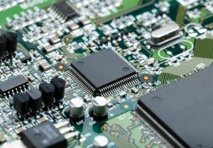
Embedded passives manufacturing runs through the entire PCB process. Core control points are concentrated in three stages. The first stage is dielectric layer patterning, requiring i-line stepper lithography with resolution of 15 micrometers or less combined with dry film photoresist such as Hitachi PFR-2000. Exposure energy is controlled at 250 to 300 mJ per square cm to balance pattern precision and dielectric layer crosslinking degree. The second stage is metallization and micro-etching, using sputtered Ti and Cu seed layers of 50 nm and 200 nm plus electroplating thickening to a total thickness of 8 to 12 micrometers, followed by Cl2 and BCl3 mixed gas RIE etching with sidewall angle greater than 85 degrees to ensure edge electric field uniformity. The third stage is lamination alignment and thermal stress management, using an optical alignment system with precision of plus or minus 3 micrometers and staged heating lamination at 120, 180, and 200 degrees Celsius with 15 minutes holding at each stage, so that interlayer displacement caused by thermal expansion mismatch is less than 1.5 micrometers. Mass production data of a certain server motherboard shows that when the lamination temperature slope exceeds 3 degrees Celsius per minute, the standard deviation of embedded capacitor capacitance drift suddenly increases from 1.8 to 4.7 percent, confirming that thermal gradient control is crucial to dielectric polarization stability.
Test Verification and Failure Mode Analysis
Embedded passives cannot undergo traditional ICT flying probe testing. A strategy combining non-contact inspection and functional verification must be relied upon. Three layers of verification are mandatorily performed in mass production. First, AOI, or automated optical inspection, identifies plate pattern bridging or gaps with a minimum defect size of 8 micrometers. Second, a microwave probe station such as Cascade Summit 12000 performs S-parameter frequency sweeping at 26.5 GHz, extracts C, ESR, and ESL parameters, and fits Cole-Cole plots to reject samples with abnormal relaxation time, where tau greater than 1 ps. Third, after accelerated aging testing at 125 degrees Celsius and 85 percent RH for 1,000 hours, retest the capacitance change rate, requiring delta C divided by C0 to be less than plus or minus 5 percent. Typical failure modes include leakage current surge caused by dielectric layer pinholes, greater than 100 nA at 10 V, tan delta increase caused by copper-dielectric interface oxidation, greater than 0.015 at 1 GHz, and interface delamination caused by thermal cycling from minus 40 to 125 degrees Celsius, where X-ray CT detection of delamination area greater than 5 percent is judged as scrap. A certain industrial PLC project once experienced accelerated capacitance decay after high temperature storage due to residual solvent in ABF dielectric, with GC-MS detecting propylene glycol monomethyl ether acetate greater than 800 ppm. It was finally solved by extending the baking process to 150 degrees Celsius for 4 hours.
Design-Manufacturing Data Chain Collaboration Mechanism
The fundamental success of embedded passives technology lies in breaking the data barrier between EDA tools and PCB factory manufacturing execution systems, or MES. It is recommended to use IPC-2581C format instead of the Gerber plus IPC-D-356 combination. This standard can natively carry metadata such as material properties of embedded capacitors and resistors including epsilon r and tan delta, structural parameters including plate thickness and dielectric thickness, and process constraints including minimum line width and spacing and allowable etching tolerance. A leading substrate factory has achieved bidirectional mapping between Cadence Allegro and MES system. The embedded capacitor BOM submitted by the design side automatically triggers in-factory material preparation, such as specifying ABF-GX batch numbers. The actual dielectric thickness measurement values from the manufacturing side, in the SPC database, are fed back in real time to the simulation platform to update model parameters. Practice shows that this closed loop increases first article pass rate from 61 to 94 percent and shortens the average engineering change order cycle by 5.3 days. In the future, with the penetration of digital twins in the PCB field, virtual fabrication based on physical models will become the core engine for improving the yield of embedded passives.
Gopcba provides professional PCB manufacturing, PCB assembly, prototype PCB assembly, low-volume PCB assembly, high-volume PCB assembly, SMT PCB assembly, through-hole PCB assembly, mixed-technology PCB assembly, flex PCB assembly, PCB design layout, components procurement, rapid PCBA prototyping, conformal coating, PCBA testing, box build assembly, wire cable harness assembly, medical PCBA, telecommunications PCBA, energy PCBA, industrial PCBA, artificial intelligence PCBA, Internet of Things PCBA, PCB capabilities, and PCBA capabilities. You can also visit our blog, learn about us, see why us, review our quality management, or contact us for more information.