Practical Notes on ESP32-C3 Vs ESP32-S3
Two of the most popular Espressif parts look similar on a pinout diagram and behave very differently once they reach the layout stage. The ESP32-C3 vs ESP32-S3 question comes up constantly in design reviews, and the usual answer about core count and price misses the point. What matters to a board designer is which radios are inside, how the pins are powered, how many high speed interfaces have to escape the package, and how much of the layout budget goes to the antenna. Get those four things wrong and the product either fails certification or overheats inside a sealed enclosure.
Two Parts, Two Very Different Boards
The ESP32-C3 is a single core RISC-V part with Wi-Fi, Bluetooth LE and a modest pin count. The ESP32-S3 adds a dual core processor, a vector unit, more GPIO, native USB, and enough memory bandwidth to drive cameras and displays. On a schematic that difference looks modest. On a board it changes the layer count, the escape routing density, the decoupling network and the thermal path under the package, which is why a layout reused from one part for the other rarely passes without edits.
Design teams that migrate a proven ESP32-C3 layout to the ESP32-S3 usually discover the problem at first power-up rather than in the schematic editor. The larger package needs more thermal copper, the extra fast buses want a solid reference plane, and the USB port needs a controlled impedance pair. Planning the ESP32-C3 vs ESP32-S3 transition as a new board instead of a spin of the old one is the cheapest decision available, and it saves a full prototype cycle.
Radio Layout and Antenna Keep-Out
Both parts share the same Wi-Fi and Bluetooth frequencies, so the RF layout rules are familiar: short traces from the module pin to the antenna, no copper under the radiating element, and a clean ground reference on the layer directly beneath. The antenna keep-out has to be respected on every layer, including inner planes that designers often forget. A ground plane that creeps into the keep-out area detunes the antenna and quietly cuts range even though the transmitter still measures normal output power.
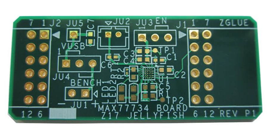
Keep the RF layout at the board edge with the antenna facing outward and away from metalwork, batteries and cables. Module data sheets specify a keep-out distance, and that figure is a minimum rather than a suggestion. Where the mechanical design puts a metal enclosure close to the antenna, place the module so the radiating element points through a plastic window. Boards used for camera products also route a camera clock near the radio, so separation and shielding of that clock deserve attention early in floorplanning.
Power Delivery and Rail Design
Power delivery is where the two parts diverge most in practice. The ESP32-C3 runs comfortably from a small regulator, while an ESP32-S3 pushing two cores, PSRAM and a camera draws short current bursts that a marginal regulator and a long thin trace cannot supply. Brownout resets that appear only when the radio transmits are almost always a power delivery problem. Measure the rail at the package pins during a transmit burst, not at the regulator output, before blaming the firmware.
Place the bulk capacitor close to the module and add local decoupling on every supply pin. Use a wide, short path from the regulator and pour copper rather than routing a thin trace, because the resistance and inductance of a narrow track turn a clean rail into a sagging one at high frequency. If the product spends most of its life asleep, check the quiescent current of the regulator as carefully as its peak rating, since battery life is set by the sleep state rather than by the transmit burst.
Routing the High Speed Peripheral Buses
The ESP32-S3 brings out interfaces that the ESP32-C3 does not, and those buses set the layout rules. Camera data lines, octal PSRAM and display interfaces all switch fast enough to need a continuous reference plane and matched lengths. Treat them as controlled impedance routes even when the clock is only tens of megahertz, because the edge rate rather than the frequency is what couples into neighbouring traces. Grouping them on one layer with a solid ground plane underneath keeps crosstalk and return paths predictable.
Where a bus must change layers, provide a return via next to the signal via so the return current has a short path. Keep switching signals away from the antenna and from analogue inputs such as sensor front ends. A useful check is to print the layout and trace the return path of each fast net by hand; if the return current has to wander across a plane split, the design will radiate. Guidance on routing high frequency traces and data buses covers the same principles in more detail.
USB, Clock and Debug Connections
The ESP32-S3 offers native USB, so the USB port becomes a real layout feature rather than a serial bridge afterthought. Route the pair as a differential line with controlled impedance and keep the two traces the same length. ESD protection belongs close to the connector rather than near the chip, and the ground of that protection device must return to the plane through a short via. Series resistors, where they are fitted, go near the source pin instead of the middle of the run.
Clocks are the other detail that trips up first builds. The ESP32-C3 uses a 40 MHz crystal and the ESP32-S3 adds a 32 kHz option for low power timing, and both need short traces, solid ground under the crystal, and no switching net routed nearby. Our notes on MCU oscillator PCB design describe the guard ring and load capacitor placement that keep start-up reliable across temperature. Bring the debug pins out to a header so the board can be reprogrammed without removing it from the enclosure.
Layer Count, Ground and Stackup
A four layer board handles either part for simple products, but the ESP32-S3 with camera and PSRAM is far happier on six layers, where a solid ground plane sits directly under the component side and a power plane serves the rails. Ground should never be split into islands joined by thin necks; every fast signal needs an uninterrupted reference. Where two grounds are unavoidable, join them at one defined point rather than letting the return current choose its own path.
Mechanical constraints often decide the stackup before electrical ones do. A compact module layout with the antenna at the edge, the regulator on the opposite side and the camera connector at the far end from the radio gives the best compromise between size and performance. The stackup and keep-out conventions used for module board design apply directly to these parts, because both are really small RF modules with a processor attached.
Prototyping, Bring-Up and Test Points
Add test points on every rail, on the enable pin and on the boot strapping pins before the first fabrication run. The strapping pins are easy to load accidentally with a pull-up intended for something else, and a board that will not enter download mode is expensive to debug without access. Leave a ground test point next to each signal point so that a scope probe has a short return, and keep the RF section free of probe pads that could detune the antenna.
For the first build, populate the minimum set of parts and verify power, clock and radio separately before fitting the camera or the display. A board that enumerates over the USB port, starts its crystal and associates with an access point has passed the difficult part of bring-up. Everything after that is application work, and any remaining problem can be measured rather than guessed at, which is exactly the position a design team wants to be in.
FAQ
Can I reuse an ESP32-C3 layout for an ESP32-S3? Sometimes, but treat it as a new board. The larger package, the extra high speed buses and the native USB port change decoupling, thermal copper and routing density enough that a direct copy usually fails its first prototype. Keep the RF and antenna sections if they already pass, and rework power, layer count and thermal design around the new part.
How many layers does an ESP32-S3 board need? Two layers work for a minimal sensor node with no camera. Four layers cover most products with Wi-Fi, USB and moderate peripherals. Six layers are the comfortable choice when camera data, octal PSRAM and a display share the board, because a dedicated ground plane and a clean power plane keep the high speed buses predictable.
Why does my board reset when the radio transmits? The transmit burst pulls a short, high current pulse through the whole supply path. A marginal regulator, a long thin trace or missing decoupling lets the rail sag below the brownout threshold. Measure at the module supply pins with a fast scope, widen the copper, add bulk capacitance close to the module, and confirm that the regulator can supply the peak rather than only the average current.