Failure Analysis: Root Cause and Escape on Assemblies
When a unit fails, the first answer is usually a guess. The failure analysis process exists to replace the guess with evidence, and it is only useful if it is followed before the unit is disturbed.
Before Anything Is Touched
The failed unit is a record. Every action taken on it destroys some of that record, so the first step is documentation: photographs, the configuration, the conditions of the failure, the run time and the environment.
The unit should be stored in a way that preserves the evidence, which usually means an antistatic bag, a desiccant and a record of who handled it. Our design release notes describe the records that should exist for the unit to be comparable with the build data.
Non Destructive Examination
The optical and X-ray examination should come before any disassembly, because it captures the state that the electrical test cannot. Solder joints, cracks, corrosion and foreign material are all visible at this stage.
The X-ray is the only way to see under a package, and it should be performed before the unit is cleaned or reworked. Our X-ray notes describe what the two methods can and cannot resolve.
Electrical Characterisation
The electrical test should be performed with the unit in as close to its failing state as possible. Where the fault is intermittent, the test should reproduce the conditions under which it appeared rather than a convenient set.
Curve tracing and time domain measurement are often more informative than a pass or fail test, because they show where the behaviour departs from a known good unit. Our short circuit notes describe how a low resistance path is localised.
Fault Localisation
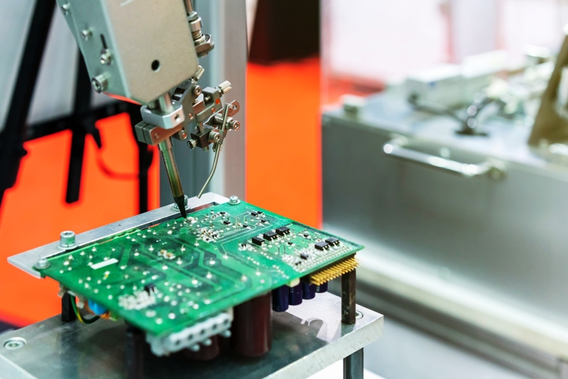
The techniques are thermal imaging, which finds a hot spot, and voltage drop measurement, which finds the path. Both should be used before a component is removed.
A component should only be removed when the evidence points at it, because removal destroys the joint evidence and it creates a new variable. Our flying probe notes describe how a net is verified without disturbing the assembly.
Physical Analysis
Cross sectioning, dye and pry, and decapsulation are destructive and should be planned rather than improvised. The section plane should be chosen to show the feature in question, and the sample should be prepared so the interface is not smeared.
The result should be photographed at a documented magnification so that a later reader can compare it with another sample.
Root Cause and Escape
The root cause is the mechanism that produced the defect. The escape is the reason the defect reached the customer, and it is a separate finding with a separate corrective action.
Both should be recorded. A corrective action that addresses only the root cause leaves the inspection that should have caught it unchanged, and the same defect will reach the customer again by a different route. Our quality notes describe how the two are tracked.
Closing the Loop
Each finding should be turned into a change that can be verified: a drawing change, a process parameter, a test limit or an inspection step. The verification is the evidence that the change worked.
Where the change cannot be verified, the finding should be recorded as accepted risk rather than as a closed item, so that it can be reconsidered when the product or the volume changes.
Process Control and Verification
Keeping a sample from the panel turns a dispute into a measurement, because the same coupon can be re-examined by both parties without rebuilding the batch. Reviewing the design before the data is released is cheaper than correcting it after the panel is in the tank, because every step downstream inherits the decision made at the front end.
Documenting the assumption is part of the design work, and a short note on the drawing prevents a question that would otherwise arrive a day later and cost a day of schedule. The process window is set by the narrowest step in the flow, so an improvement anywhere else shows up as margin rather than as yield until that step is addressed.
A short note on the drawing about handling, storage or packaging is often worth more than an extra decimal place on a tolerance. Where a value sits close to a process limit, the drawing should say so, since the shop can then open the process window rather than working to a nominal figure that carries no tolerance.
Checks Before Release
The checks that matter are the ones performed on the product rather than on a sample kept for the purpose, because a coupon that travels with the panel is the only evidence about that panel. Where a requirement can be measured, it should be measured at the point of manufacture and recorded against the board or the lot it applies to.
A parameter that is set once and never re verified drifts, and the drift is usually discovered by a defect rather than by the record. The tooling, the material and the profile form one system, and a change to any of them should be assessed against the other two before it is released.
Where the process window is narrow, the measurement resolution has to be better than the window, or the data cannot distinguish a good part from a marginal one. A record that identifies the operator, the date and the settings is worth more than a record that identifies only the result.
Verification and Records
The acceptance criteria should be written before the work starts, so that the decision is made by the specification rather than by the person inspecting. Where an operation cannot be verified afterwards, it has to be controlled during the operation, and that control has to be visible in the record.
Sampling is a compromise between cost and confidence, and the sample size should follow from the failure rate that has to be detected.
FAQ
Should the customer be asked to return the failed unit? Yes, wherever possible, because a description of a failure is not the same as the unit that failed. The unit carries the evidence that the description omits.
How many samples are needed? One sample identifies a mechanism; several samples show whether it is systematic. Where the failure is intermittent, the number should follow the failure rate.
What does gopcb provide for failure analysis? We provide documented receipt and storage of failed units, non destructive optical and X-ray examination, electrical characterisation against a known good unit, thermal and voltage drop localisation, planned cross section and dye and pry, and root cause and escape records with verified corrective actions.